
A Chart By Polar
CWNA Chapter 5 is a big one with a lot of content, so best grab your favorite beverage, sit in a comfy chair and get ready. Don’t despair though, we will look at a lot of pretty pictures along the way! Let’s get started.
To kick things off, the first item of business is to discuss polar charts. No, this is not how we would attempt an expedition to the North Pole, it is a chart on which Azimuth and Elevation are plotted. Most antenna vendors will provide this as part of their documentation so you can get an idea of how the signal propagation will look. If you have ever had the chance to play with Ekahau Pro then you have likely run into polar charts before when doing predictive designs.
Azimuth: Also known as the H-plane is a top view of the radiation pattern of the antenna. Omnidirectional antennas would present as a circle since they radiate signal evenly outward. It would be like Homer Simpson floating in the air looking down at a donut! You will hear Omnis and the comparison to donuts a lot.

The beam pattern is in the horizontal plane, so for this, let’s move to a bagel. It would be like slicing the bagel from side to side and taking off the top and looking down. You would see the center hole and a perfect circle around the edge.
Elevation: Also know as the E-plane. This antenna pattern is shown as a side view. This is a vertical orientation. Let’s visit the bagel again. Keeping with the Omni theme, we cut the bagel like we are getting two halves of a sandwich, once you open it up we see it from the side. It would basically look like two circles joined in the middle.
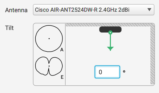
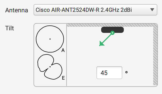
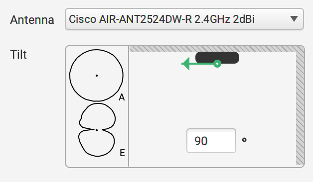
Take a look at the screen shots I took from Ekahau Pro 10. This shows the signal pattern of a Cisco AIR-ANT2524DW-R Omni antenna. The black oval at the top is the antenna, and the green arrow shows in what degree the antenna is tilted. Let’s start with the first picture. You can see here that we have the antenna angle at 0 degrees meaning it is mounted flat on the ceiling pointed straight down. If you look just to the left you will see an “A” for Azimuth and an “E” for Elevation. Notice here the Azimuth is like we described, a perfect circle and the Elevation looks like a bagel cut down the middle. Maybe this bagel didn’t cook quite right but whatever. If we move to the next picture the only thing that has changed is we told Ekahau that the antenna is now tilted at a 45 degree angle. You see the Azimuth does not change but the Elevation now moves with the angle of the antenna. The same goes for picture three, where we have now changed it to a 90 degree angle in which the signal is basically on its side. It is not recommended to use omnis at an angle as the signal is meant to propagate out evenly in all directions. When mounted at an angle you are sending signal into the ceiling that cannot be used. More on proper antenna selection shortly. If you were curious about deciphering Cisco antenna model numbers here it is. For this model AIR-ANT2524DW-R, we take the first two numbers “25” which tells us it is 2.4GHz and 5GHz. The second set of numbers “24” tell us the antenna gain, in this case 2dBi for 2.4GHz and 4dBi for 5GHz.
Beamwidth: this is the measurement of how broad or narrow the focus of an antenna is, and is measured both horizontally and vertically. It is measured from the center or strongest point of the antenna to each of the points along the horizontal and vertical axes, where the signal decreases by half power (-3db). Take a look at the picture below. We can see that the first circle from the outside edge is -5dBm, just just about half way between that line and the outer edge is the -3dBm line. You can then see where the outer edges of the lobe hit that line on the left and right side. These are the points that determine your beam width.

You Get an Antenna, and You Get an Antenna
When it comes to antennas, there are truly a lot of options. Not only are there many styles of antennas, but also many variations of each style. Each of these variants have their place when used appropriately. It takes a skilled wireless design engineer to use antennas to garner the best results for a particular scenario.
Antenna Types: Horizontal Beamwidth Vertical Beamwidth
- Omnidirectional 360 degrees 7-80 degrees
- Patch/Panel 30-180 degrees 6-90 degrees
- Yagi 30-78 degrees 14-64 degrees
- Sector 60-180 degrees 7-17 degrees
- Parabolic Dish 4-25 degrees 4-21 degrees
Omnidirectional Antenna: An omni antenna as previously discussed radiates signal in all directions. Refer back to the bagel analogy. If you have every seen the black rubber duck antennas, commonly seen on higher end home wifi routers, they are dipole omni antennas.
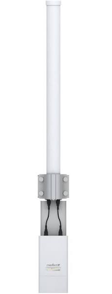
Ubiquiti high gain Omni antenna
Semi Directional Antenna: This antenna directs RF in a specific direction, and has a short to medium range. It is commonly used for providing a network bridge between buildings. Types of semi directional antennas are patch, panel, and yagi.
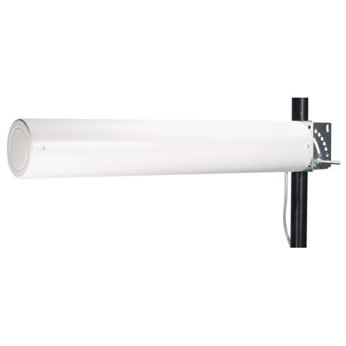
Yagi high gain antenna
Parabolic Dish: If you have seen a satellite dish antenna on a house, you would have a pretty close approximation of what a parabolic dish antenna looks like.
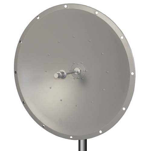
Parabolic Dish Antenna
Grid Antenna: A grid antenna basically is an open grill with the edges curved. This antenna is used for bridge links and is highly directional. The grid allows this antenna to combat wind, which is very helpful with point to point links as the tolerances for maintaining a connection are very tight. Highly directional antennas benefit from narrow beamwidths allowing for much greater distances.
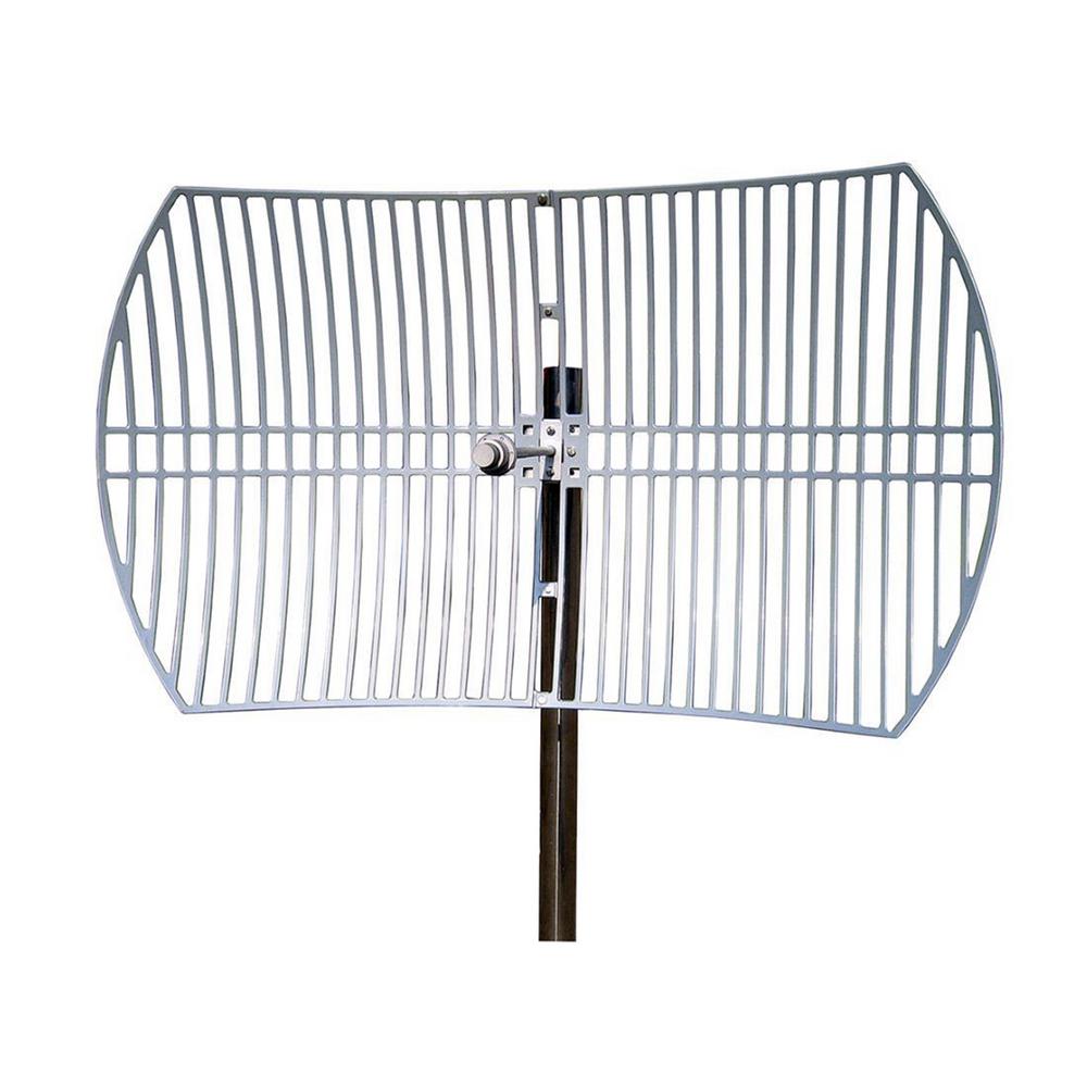
Grid Antenna
Sector Antenna: A sector antenna is a high gain, semi-directional, pie shaped RF pattern. Using sector antennas you could use multiples of the same model to achieve 360 degree coverage, known as a sector array. Typical antennas would have a decent amount of back lobe output but sector antennas do not. Horizontal beamwidth on a sector antenna is normally around 60-180 degrees with a vertical beamwidth of 7-17 degrees. You would normally associate this with the ring of antennas you see on cell phone towers.
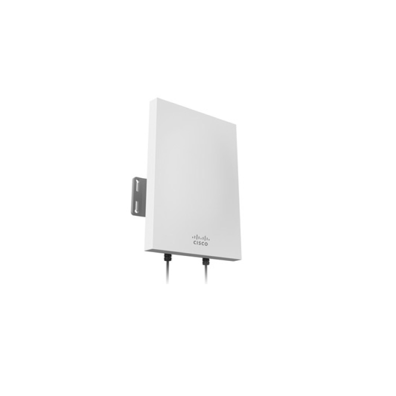
Meraki MA-ANT-23 Sector Antenna
Antenna Array: An antenna array is a group of two or more antennas that are integrated together to provide coverage. They work together to perform beamforming (method of concentrating RF energy). The three types of beamforming are as follows…
- Static Beamforming: This type of beamforming uses directional antennas to provide a fixed radiation pattern. In this case we use multiple directional antennas clustered together that are all aimed away from a center point.
- Dynamic Beamforming: Here we focus RF energy ins a specific direction and in a particular shape. The pattern can change on a frame by frame basis using an adaptive antenna array (beam steering).
- Transmit Beamforming: In this scenario we are using digital signal processing , not antenna technology to increase our output. We are transmitting multiple phase-shifted signals in hopes that they arrive in phase at the place the transmitter thinks the receiver is located. This process is accomplished using two or more antennas, duplicating the signal to improve gain.
Battling the Bulge
No, I don’t think the earth is flat. If I did, everything I am reading is a lie, and I can just point antennas at each other and be fine. Physicist Augustin Jean-Fresnel would have some explaining to do! Let’s talk about some considerations we need to take into account when planning medium to long range point to point bridge links.
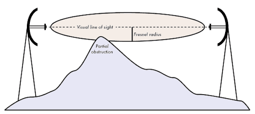
We first need to talk about the Fresnel Zone. The Fresnel Zone in the imaginary, elongated, American football shaped area that surrounds the path of the visual line of site between two point to point antennas. It has multiple zones from the middle outward. All odd numbered zones are in phase with the point source signal, and all even numbered zones are out of phase. It is also important to note that no object should enter into more than 40 percent of the first Fresnel Zone. Antenna type and beamwidth have no bearing on the Fresnel Zone. As you can see below, we are looking at the first Fresnel Zone and the visual line of sight is represented. It is important to note that visual line of sight cannot be relied upon for RF transmissions. We can however, take into account RF Line of Sight, which is the area around the visual line of sight. Additionally we can see how an object can impede into the zone.
Flat Earthers, it is time to skip ahead a paragraph. Our next item to take into account is Earth Bulge. The Earth is round, seriously, and because of that fact it is a variable we need to consider in point to point links due to the curvature of the Earth. This comes into play for links seven miles or more apart. Picture time again! Below you can see where they have accounted for the 60 percent Fresnel radius at the edge of the Earth Bulge. We can also take a look at antenna height here as well. Antenna height requirements are as pictured, we need to have 60 percent of first Fresnel Zone available, take into account the Earth Bulge, and look at the height of any obstacles that may encroach into the Fresnel Zone and their distance from the antenna. Not pictured is antenna polarization. Antenna polarization is the alignment or orientation of the waves which can be either vertically or horizontally polarized. The orientation of the antennas does not matter as long as they are both oriented in the same manner.
Antennas, Antennas, Read More About Them
Antenna diversity exists when an access point has two or more antennas with a receiver together to minimize the negative effects of multipath.
Types of Antenna Diversity:
- Switched Diversity: Listens with multiple antennas, picking the one with the best signal. It receives multiple copies but defaults to the best. If the signal drops below a predefined threshold it will switch to a different antenna.
- Receive Diversity: Listening for the best received signal
- Transmit Diversity: Transmitting out of the antenna where the last best received signal was heard.
We will get into MIMO ( Multiple Input Multiple Output) much more deeply in future chapters but for now there are a couple things to get us started. MIMO takes what normally is a degrading issue in multipath and uses it to its advantage. It can receive or transmit using multiple antennas concurrently. Also it uses signal processing techniques to enhance reliability, range and throughput. 802.11n is when this was introduced and 802.11ac also supports it.
Antenna Mounting Considerations:
I am not going to get too deep into the mounting considerations as I feel these are pretty self explanatory but the highlights are listed below.
- Placement
- Mounting
- Appropriate use and environment
- Orientation and alignment
- Safety
- Maintenance
Let’s Dress Up that Antenna
When you are tasked with installing an antenna there are some items that will possibly be required. The first and most likely to cause the biggest impact to your signal are cables. Cables always have a negative impact on your signal strength and need to be accounted for. We also need to make sure we impedance match to the antenna and transceiver. Finally we need to understand that as the frequency used increases, so does the increase in attenuation, so 2.4GHz will attenuate less than 5GHz. Just like the cables, connectors also need to be impedance matched and typically add 1/2db of insertion loss for each connection.

Next up we have splitters. Splitters are a connector or cable that divides an RF signal into two or more separate signals. They are typically only recommended to be used by very knowledgeable RF engineers.
Amplifiers: They take the signal generated by the transceiver, increase it, and send it to the antenna. This is considered active gain. Amplifiers typically raise the noise floor by 10db or more. Types of amplifiers found below:
- Fixed Gain: output of transceiver is increased by the amount of the amplifier
- Fixed Output: does not add output to the transceiver. It generates a signal equal to the to output of the amplifier, regardless of transceiver power
Attenuators: These have the opposite result of amplifiers. They are designed to absorb energy, decreasing the signal as it travels through the cable. There are two types, fixed loss with has a set db loss value, and variable loss which has an adjustable db loss either via a dial or switch.
Lightning Arrestors: These are there to redirect transient currents caused by nearby lightning strikes or ambient static away from electronic equipment and into the ground. They protect against surges of 5000amps or 50 volts and are not designed to protect against direct lightning strikes.
Grounding Rods and Wires: Made up of a grounding rod and wires, these provide a low impedance path to the ground. If you have ever been in a network closet you most likely have seen grounding straps that tie all the equipment to a central grounding location.
VSWR (Voltage Standing Wave Radio): This is the measurement of the change in impedance to an AC signal. It is calculated by the numerical relationship between the measurement of the maximum voltage along the line and the measurement of the minimum voltage along the line. The end result is decreased signal strength, erratic signal strength and even transmitter failure.
End of Chapter Review
In this chapter we learned about polar charts and how to read them. We explored the types of antennas that we have at our disposal to meet different client requirements. We also dove into how the signal is propagated from the antenna and how different antennas affect the pattern. Outdoor long distance links made an appearance where we got into the Fresnel Zone and what is important in designing point to point links. And last but not least we learned about what types of connectors are available for antennas and the affect they have on the signal. This chapter was quite large with a lot of information to put out there. Keep in mind that the content I am providing are notes for things I find I need to ingrain deeper and are not meant to be all encompassing of each chapter. As always, please share, retweet and keep following along.


Good work!!
Thanks so much Javier!
Excellent! I’m pretty much reading the book at the same pace/sections as you, making notes in onenote. I was going to blog, but this is perfect for review at the end of a chapter! Thanks for this!
Great to hear Daniel. I want to be moving a bit faster, but I have been writing notes with pencil and paper, then using the notes to write the blog, rinse and repeat. I am hoping it helps solidify things for me. I almost wish I had done notes on the computer but I would get too distracted with access to the internet so easily lol.