
CWNA Chapter 10: Beamform me up Scotty
In the last chapter we discussed 802.11 MAC, in which we went through how 802.11 frames moved through the layers of the network and what they contain. Today we will be reviewing MIMO (Multiple-Input, Multiple-Output) technology, where we learn how we take a destructive element in multipath and use it to our advantage.

A quick aside before we get started. In Chapter 8, I had mentioned feeling scattered and all over the place. It didn’t go away with more sleep, it didn’t go away with more coffee. I took a look at why I couldn’t focus and tried to come up with a why. It became clear to me that after a a full day of work and family, that studying late at night as I was attempting to do, was causing my focus to be off. So this week I am trying something new. I am getting up at 4am and trying to put in work till around 7:15. I get up, get some coffee, let the dog out and get to it. If I need to finish up something I didn’t get accomplished, I will do it from 7-8pm. From 8-9pm I try to hang out with the kids. By 9:30pm, I am going to bed. Why should you care? I am telling you this to give you something to try if other things are not working. You need to find out what works for you. We are all different, we learn different, and we have different lifestyles. I felt myself slipping off the tracks and needed a kick back on. I feel great and alert early in the morning, so it is working for me. Okay, I am done. Those of you that said NOPE, NOPE, NOPE, I get it. You do you!
MIMO (Multiple-Input, Multiple-Output)
Before we jump in, let’s go over two quick items we need to remember. First 802.11n defines HT (High Throughput) and 802.11ac defines VHT (Very High Throughput). Those will be very important to be able to differentiate between the different topics we are going to discuss. Knowing which PHY type applies to different areas is critical here.
MIMO exists at the PHY layer using multiple radios and antennas, called radio chains. As we have already mentioned, it was created to combat the negative effects of multipath turning that negative into a positive. MIMO is able to take advantage of mulitpath using DSP (Digital Signal Processing) and a method called spatial multiplexing.
Radio Chains
When we take a look at legacy radios, we need to know that they us SISO (Single-Input, Single-Output). A radio chain is a single radio and all its supporting architecture, including mixers, amplifiers, and analog/digital convertors. In contrast a MIMO radio chain consists of multiple radio chains.
- When you see an AP rated with “2 x 3 MIMO”, this equals 3 radio chains with two transmitters and three receivers. Looking at the numbers, the first one is always references the transmitters and the second number the receivers.
When it comes to radio chains, more transmitters equals more data, and more receivers equals a higher SNR. MIMO allows for up to 4×4 using four radio chains in 802.11n. 802.11ac allows for up to eight radio chains.
Spatial Multiplexing
Spatial Multiplexing is when you are sending multiple independent streams of unique data using spatial diversity. It is also known as spatial diversity multiplexing. When you have independent data streams, they are know as spatial streams. Multiple streams following different paths to the receiver because of the space between the transmitting antennas is know as spatial diversity.
- Examples of WiFi three number syntax for MIMO
- 3×3:2 = 3 transmitters, 3 receivers and 2 spatial streams
- 3×3:3 = 3 transmitters, 3 receivers and 3 spatial streams
- If a 3×3:3 AP and a 2×2:2 station communicate, only 2 spatial streams will be used for unicast transmissions
MIMO Diversity:
The first item to discuss in MIMO diversity is Switched Diversity. Switched Diversity is when SISO radios listen with multiple antennas when receiving RF signals. In this case multiple copies of the same signal arrive at the receiver with different amplitudes, and the one with the best amplitude is chosen. When transmitting ti will use the antenna from which the last strongest amplitude was heard.
Next we have receive diversity which may use Maximal Ratio Combining (MRC). When receive diversity is used, the signals may also be linearly combined with this signal processing technique. It is used to combine multiple received signals by looking at each unique signal and combining them in a method that is additive not destructive.
Space-Time Block Coding
Space-Time Block Coding is a method where the same info is transmitted on two or more antennas, but the number of antennas must be even. This is a type of transmit diversity and is only possible between MIMO devices.
Transmit Beamforming (TxBF)
TxBF allows a MIMO transmitter using multiple antennas to adjust the phase and amplitude of the outgoing transmissions in a coordinated method. With the adjustment in phase and amplitude, it allows the signals arriving at the receiver to be in phase, resulting in constructive multipath. Essentially this is emulating a directional antenna. The end result is a higher SNR and better received amplitude. Transmitters using beamforming will try to adjust the phase of the signals based on feedback from the receiver by using sounding frames. This exchange is used to measure the RF channel and create a computative assessment on how to better steer RF energy to a receiver. This assessment is called a steering matrix.
Transmit Beamforming relies on either implicit feedback or explicit feedback from the receiver and transmitter.
- implicit feedback: the beamformer sends a sounding frame and then receives long training symbols transmitted by the beamformee. No direct feedback is received from the beamformee. This is similar to sonar in which a submarine sends out a signal and it bounces off another vessel and comes back. The other vessel was not engaged in this process.
- explicit feedback: the bemformee makes a direct estimate of the channel from training symbols sent to it buy the beamformer. The beamformee creates the steering matrix. This is not widely adpoted in 802.11n but is used in 802.11ac.
802.11ac Explicit Beamforming
With 802.11ac Explicit Beamforming both the AP and the client must support it. This uses an interactive calibration process to identify how to perform the transmission using the multiple radio chains, know as channel sounding. The process is as follows:
- Beamformer sends a null data packet announcement frame.
- Beamformer then follows with an NDP frame.
- Beamformee processes each OFDM subcarrier and creates feedback containing info regarding power and the phase shift between each pair of transmit and receive antennas.
- This info is used to create a feedback matrix which is compressed and sent back to the beamformer.
- Last, the beamformer used the feedback matrix to calculate a steering matrix, which is used to direct the data transmission to the beamformee.
Multi-User MIMI (MU-MIMO)
MU-MIMO allows an AP to communicate with up to four devices at a time. This is 802.11ac only, and not all support it. The goal is to use as many spatial streams as possible, whether to one client or to four. It is important to note that this is for downstream traffic only.
Five number syntax used sometimes for MU-MIMO
- Example: 4×4:4:3:3
- Let’s look at the number after the colon. The first number “4” represents 4 spatial streams for SISO, the second number “3” represents 3 spatial streams for MU-MIMO, and the third number “3” represents 3 clients for MU-MIMO
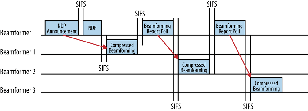
Multi-User Beamforming
Process:
- AP transmits NDP announcement, notifying multiple beamformees of intent.
- AP follows with NDP frame.
- Each beamformee processes OFDM subcarrier and creates feedback info, creating a compressed feedback matix.
- The first beamformee responds to the AP, then the AP polls each additional beamformee sequentially using Beamforming Report Poll frames.
- AP then uses the feedback matrix from each to create a single steering matrix.
- After the AP transmits the multiuser frame, each client must ACK its frame with a Block-ACK, since all 802.11ac frames are A-MPDUs. As before, this is done sequentially.
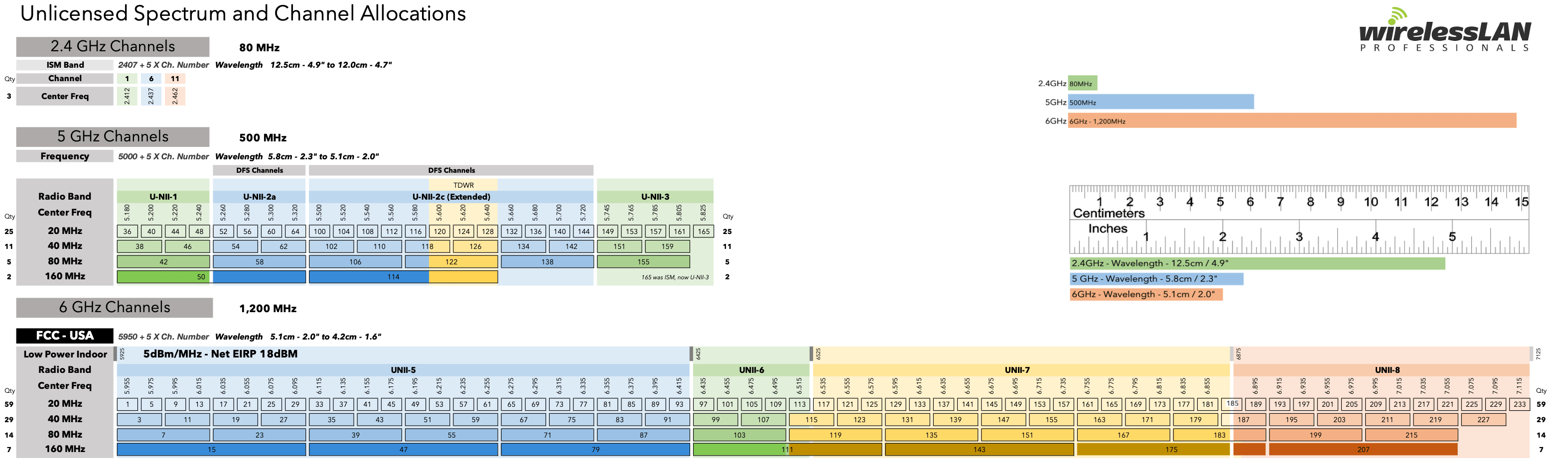
Channels
Before we dive in, check out the chart below from WLAN Professionals. This chart covers some items outside the scope of the CWNA, but it a great visual for looking at available channels. For the scope of our studies, we are only concerned with 20, 40, 80, and 160MHz channels in 2.4GHz and 5GHz. With OFDM channels used by MIMO radios, we use more sub-carriers which allows them to be bonded together. Because of this, it allows for higher data rates and more potential throughput. Although you could bond two 20MHz channels in 2.4GHz to create a 40MHz channel, this would leave you with only one possible channel, so using only 20MHz channels is recommended.
20MHz Channels
When it comes to 20MHz channels for 802.11a and 802.11g, it is the only option. There are 64 subcarriers, 48 of which transmit data, 4 used for pilot tones for calibration between transmitter and receiver and the remaining are not used. This changes with 802.11n and 802.11ac, which also can use 20MHz channels, but add 4 extra data subcarriers for a total of 52, allowing for higher throughput.
40MHz Channels
When we move up to 40MHz channels we are now in the realm of 802.11n and 802.11ac. There are 128 subcarriers, 108 for data, 6 for pilot tones and 14 unused. This doubles the bandwidth over 20MHz. Since we are now bonding two 20MHz channels together, we have a primary and secondary 20MHz channel which must be adjacent. For example, channel 36 and 40 together, known as 36+1. You will notice the positive offset in the previous statement. We can also have a negative offset, for example 40-1 would be a primary channel of 40 and secondary of 36. When we move to 802.11ac we no longer use offsets, just a center frequency. When it comes to management frames, they will only be sent from the primary channel. Additionally data transmissions between 802.11n/ac APs and 802.11a/g clients will only use the primary channel.
40MHz Intolerant
As stated previously using 40MHz channels in 2.4GHz does not scale so we need to discuss a way to combat someone using 40MHz channels nearby on 2.4GHz. 40MHz Intolerant is a protection against just that. Your AP can advertise it is 40MHz intolerant in 802.11n management frames in an attempt to force the other AP back to 20MHz channels.
80 and 160 MHz Channels
80MHz channels are 4 20MHz channels with 256 subcarriers, 234 of which are for data, 8 for pilot carriers and 14 unused. 160MHz channels are made up of 2 80MHz channels, but they don’t need to be adjacent. If they aren’t they are called 80+80MHz channel. 160MHz channels consist of 512 subcarriers, 468 for data, 16 as pilot carriers and 28 unused.
Guard Interval
Guard interval is a period of time between symbols that accommodates the late arrival of symbols over long paths. 802.11a/g radios use a 800 nanosecond guard interval. The guard interval should be 2-4 times the length of the delay spread. In most cases a 400 nanosecond guard interval is sufficient and is referred to as a short guard interval. This typically results in a 10% increase of data rates due to the shorter symbol time.
256 QAM Modulation
In our previous review of chapter 6, we discussed a lot of different modulation techniques but just touched on QAM 256. Let’s dive into some features. 256 QAM was introduced in 802.11ac and identifies 256 unique values, 16 different phase shifts and 16 different levels of amplitude shift. It is more sensitive to noise and interference, which means that 802.11ac receiver performance requires about 5db of additional gain over 64 QAM. 802.11ac is only for 5GHz but some WLAN vendors offer support for 256 QAM for 2.4GHz, but clients would need to support it.
802.11n/ac PPDUs
- Non HT: Legacy format that consists of a preamble that uses legacy short and long training symbols for synchronization. It is mandatory in 802.11n and transmissions can only occur in 20MHz channels.
- HT Mixed: The preamble contains non-HT training symbols and legacy signal field, which can be decoded by 802.11a/g radios. The rest of the HT Mixed preamble and header cannot. HT Signal (HT-SIG) contains info about MCS frame length, 20 MHz or 40MHz channel, frame aggregation, guard interval and STBC. HT-STF and HT-LTF are used for synchronization between MIMO radios. HT Mixed is mandatory for 20 and 40MHz channels. All broadcast traffic must be sent on 20MHz for 802.11a/g non-HT clients.
- VHT: In VHT the preamble is compatible with 802.11a/g radios. The Non-VHT portion of the PHY header can be understood by 802.11/g devices, while the VHT portion can only be understood by 802.11ac radios.
802.11n/ac MAC
- A-MSDU: This is a method of frame aggregation in which multiple MDSUs can be aggregated into a single frame transmission.
- Frame aggregation is a method for combining multiple frames into a single frame
- individual MSDUs must be of the same QOS catagory
- most 802.11n chipsets implemented A-MSDU
- uses ACKs for delivery notification
- Frame aggregation is a method for combining multiple frames into a single frame
- A-MPDU: Using A-MPDU, we have multiple MPDUs aggregated into a single PPDU transmission. All of the MPDUs must have the same receiver address and must all be of the same QOS category just like A-MSDU. In this instance we will be using Block-ACKs for delivery notification. Unlike A-MSDU if a single frame fails, only that individual is corrupted and the rest of the MPDUs will complete. All 802.11ac frames use A-MPDU even if only a single frame is being sent.
- Block ACK: This is a method of acknowledging multiple individual 802.11 frames during a frame burst. It is needed to cover the multiple MPDUs that are aggregated inside a single A-MPDU transmission. As mentioned previously, if a frame fails in A-MSDU, all frames need to be resent. In A-MPDU, if any frames fail, only the failed frame needs to be resent, making A-MPDU much more efficient.
Power Management
802.11n/ac radios still support a basic power-save mode, based on the original 802.11 power-management mechanisms. There are two power save management methods:
- Spatial Multiplexing Power Save (SM Power Save): allows a MIMO radio to power down all but one of its radios. This method has two operations, static and dynamic.
- Static SM: basically turns the AP into a SISO radio and returns to normal using a SM power save action frame.
- Dynamic SM: also powers down all but one radio, but can return all its radios much more quickly. An AP can trigger it by sending a RTS frame. The client then wakes up the radios and sends a CTS frame back to the AP.
- Power Save Multi-Poll (PSMP): this is an extension of APSD defined by the 802.11e amendment.
VHT TXOP Power Save: introduced in the 802.11ac amendment, this allows a client that sees a TXOP that is allocated to another client causing it to turn off its radio during the duration of that transmission.
Modulation and Coding Scheme
802.11a/g uses data rates from 6 to 54Mbps, based on the modulation and coding method used. HT radios define data rates based on numerous factors, including modulation, coding method, the number of spatial streams, channel size, and guard intervals. 77 modulation and coding schemes (MCS) exist for both 20MHz HT channels and 40MHz channels. Eight of these are mandatory. VHT radios simplified this with only 10 MCS options, of which the first 8 are mandatory.
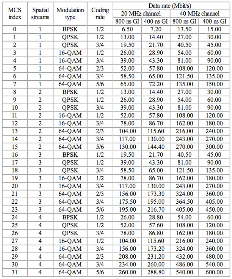
- 802.11ac Data Rates: 802.11ac claims speeds up to 6933Mbps and the first enhancement that allows for that to be possible was the previously discussed 256 QAM. MCS9 only works with 40, 80 and 160MHz channels and each MCS can use up to 8 spatial streams and 4 different channel widths. A consideration we must think about is that when we combine channels, we increase throughput, as well as gaining a little more channel space from the area between the bonded part of the channels. This explains why going to a 40MHz wide channel has a 2.1X multiplier, and a 80MHz wide channel has a multiplier of 4.5X. You would assume that a 160MHz channel would be more than twice that of an 80MHz channel, but due to the fact that a 160MHz channel is two 80Mhz channels that don’t have to be adjacent you only double to 9X. When we get into VHT data rates, they depend on things like guard interval, spatial streams and channel width.
If you take a look at the chart below, you will be able to see the impact all of the variables have on throughput including channel width and guard interval. If you do the math on the difference between an 800 nanosecond guard interval and a 400 nanosecond guard interval, you will see we are very close to the 10% increase discussed earlier.
HT Protection Modes (0-3)
To ensure backward compatibility with older 802.11a/b/g radios, 802.11n/ac APs may signal to other 802.11n/ac stations when to use one of 4 HT protection modes. The four possible settings referenced above are 0-3. These settings can dynamically change depending on devices that are nearby or associated to the 802.11n/ac AP.
- Mode 0 – Greenfield (No Protection) Mode:
- only HT radios in use
- all clients must have the same operational capabilities
- if conditions are not met, there is no need for protection
- Mode 1 – HT non-member Protection Mode:
- all stations must be HT in the BSS
- protections kick in when a non-HT client station or non-HT AP is heard that is not a member of the BSS
- Mode 2 – HT 20MHz Protection Mode:
- all the stations in the BSS must be HT stations and are associated to 20/40Mhz AP
- if a 20MHz only HT station associates to the 20/40MHz AP then protection must be used
- Mode 3 – Non-HT Mixed Mode:
- used when one or more non-HT stations are associated to the HT AP
- BSS can be either 20MHz or 20/40MHz capable
- if any 802.11a/b/g radios associate to the BSS, protection will be used
WiFi Alliance Certification
The WiFi Alliance maintains a certification program for 802.11n call WiFi CERTIFIED n along with one for 802.11ac called WiFi CERTIFIED ac. Products must support WMM, QOS, and WPA/WPA2 security mechanisms.
Check out the following links for more information on these two certifications
Mandatory Features:
- Support for 2 spatial streams: APs are required to transmit and receive at least two spatial streams. Client stations are required to transmit and receive at least 1 spatial stream.
- Support for A-MPDU and A-MSDU in receive mode and A-MPDU in transmit mode. This is required for all devices
- Support for Block-ACK. This is also required for all devices. As a refresher, this is when the device sends a single Block ACK frame to acknowledge multiple received frames.
Mandatory Features:
- Channel width of 20/40/80MHz
- Modulation and Coding scheme: MCS 0-7
- Spatial streams: one for client and 2 for APs
- Guard Interval: Both Long (800 nanoseconds) and Short (400 nanoseconds)
Chapter Review
In this chapter we took a look at MIMO as well as MU-MIMO and what is required to make them work. We took a look at channel widths and how that relates to bandwidth. We saw how MCS rates are affected by things like channel width and guard interval. Lastly we came to understand what is required by the WiFi Alliance to certify 802.11n and 802.11ac.
Up next is the CWNA Chapter Review of WLAN Architecture, where we will get into WLAN client devices, management/control/data planes, specialty WLAN infrastructure, cloud networking, infrastructure management and APIs. See you then!


Really enjoyed this.
It was playing on my mind how an AP could use multiple antennas but too many APs causes interference.
Makes more sense now. Thankyou
Thanks Phil, glad it helped provide clarity!