
CWNA Chapter 9: 802.11 MAC
Todays featured image is a throwback to my high school days. I can’t believe that “Return of the Mack” came out in 1996, technically a year after I graduated high school. Enough memory lane, let’s try to get this post moving. In the last chapter “Medium Access”, we talked about how wireless works over the medium. In this chapter we will be discussing the 802.11 MAC frame format.
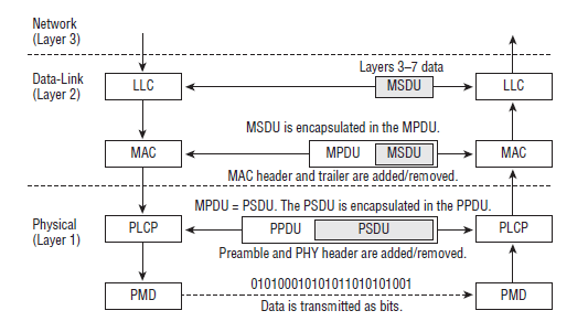
Data Link Layer
The 802.11 Data Link layer is divided into two sublayers. The upper portion is the 802.2 Logical Link Control (LLC) sublayer. The bottom is the Media Access control (MAC) sublayer.
MAC Service Data Unit (MSDU)
When layer 3 sends data to the Data Link layer, that data is handed off to the LLC and becomes known as the MAC service data unit (MSDU). It contains data from teh LLC and layers 3-7. The MSDU is the data payload that contains the IP Packet plus some LLC data. Only 802.11 data frames carry and MSDU payload in the frame body. The maximum frame size of the MSDU was 2304 bytes, but 802.11n introduced Aggregate-MSDU (A-MSDU), which bumped it up to 3839-7935 bytes, depending on the stations capability plus any overhead from encryption.
MAC Protocol Data Unit
After the LLC sublayer sends the MSDU to the MAC sublayer, the MAC header info is added to the MSDU to identify it. It is at this point that the MSDU is encapsulated in a MPDU. The MPDU is an 802.11 frame and has three components listed below.
- MAC Header: Frame control info suration info, duration info, MAC addressing, QOS control info, and HT control info are all found here.
- Frame Body: MSDU upper-layer payload is encapsulated in the frame body
- Frame Check Sequence: Compromises a 32 bit cyclic redundancy check that is used to validate the integrity of received frames.
Physical Layer
The Physical Layer is divided into two sublayers. First is the upper portion, known as the Physical Layer Convergence Procedure (PLCP) sublayer. In the lower portion we have the Physical Medium Dependant (PMD) sublayer.
- PLCP Service Data Unit (PSDU): this is the view of the MPDU from the Physical Layer. The MAC layer refers to the frame as a MPDU, where the Physical Layer refers to the same frame as a PSDU.
- PLCP Protocol Data Unit (PPDU): When the PLCP receives the PSDU, it then prepares the PSDU to be transmitted and creates the PLCP Protocol Data Unit. PLCP adds a preamble and PHY header to the PSDU.
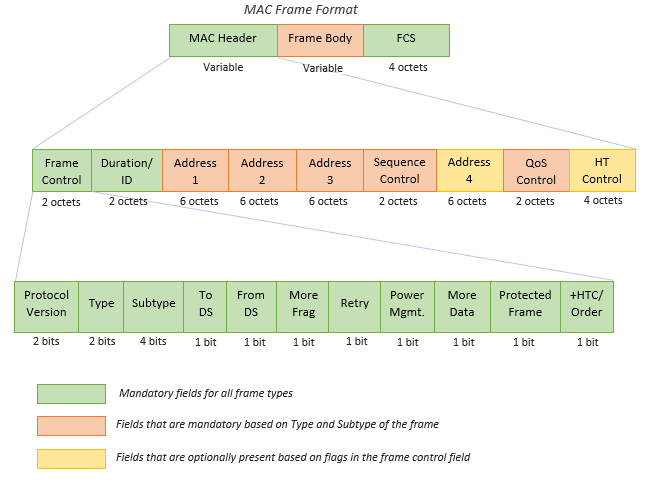
802.11 MAC Header
Within the 802.11 MAC Header we have 9 major fields, four of which are used for addressing. The rest are Frame Control field, Duration/ID field, Sequence Control field, QOS Control field, and HT Control field.
- Frame Control field: Takes up first two bytes of the MAC header. Within these first two bytes are 11 subfields.
- 11 subfields: Protocol Version, Type, Subtype, To DS, From DS, More Fragments, Retry, Power Management, More Data, Protected Frame and HTC/Order.
- Protocol Version field: This is a 2 bit field placed at the beginning of all 802.11 MAC headers denoting which protocol version is being used by the frame. Currently only one version exists, so it is set to 0.
- Type field: Identifies whether the frame is a management, control, data, or extension frame. It is also 2 bits.
- 00 – Management frame – used to discover APs and join BSS
- 01 – Control frame – used to ACK successful transmissions and reserve wireless medium
- 10 – Data frame – used to carry upper layer MSDU payload
- 11 – Extension – new, flexible format, currently only used with 802.11ad
- Subtype field: helps further identify types, since there are variations of management, control, and data.
- Retry field: this is a single bit, and if set to 0, it is the original transmission. If it is set to 1 in either data or management, the transmitting radio is indicating that the frame being sent is a retransmission.
- Protected Frame field: Also a single bit, it is used to indicate whether the MSDU payload of a data frame is encrypted. When set to 1, it is encrypted. Does not specify an encryption.
- Duration/ID field: The duration value in the MAC header of a transmitting station is used to reset the NAC timer of other listening stations.
Some additional reading I would recommend is a blog from CWNP in which they do a 3 part series on 802.11 MAC found HERE!
MAC Layer Addressing:
Within MAC Layer Addressing we have two types:
- Individual Address: assigned to unique stations on the network. AKA unicast address.
- Group Address: multiple destination address could only be used by one or more stations on the network. There are two types here as well.
- Multicast-Group Address: used by an upper layer entity to define a logical group of stations
- Broadcast Address: group address that indicates all stations that belong to the network
802.11 MAC address fields:
- Source Address (SA): MAC of original sending station
- Destination Address (DA): MAC of final destination of the L2 frame
- Transmitter Address (TA): MAC of 802.11 radio that is transmitting the frame onto half-duplex 802.11 medium
- Receiver Address (RA): Mac of 802.11 radio that is intended to receive the incoming transmission from the transmitting station.
- Basic Service Set Identifier (BSSID): MAC that is the L2 identifier of the BSS.
To DS/From DS field:
Each of the To DS/From DS fields are 1 bit and control the meaning of the four MAC address in an 802.11 header discussed above. Additionally they indicate the flow of the 802.11 data frames between the WLAN and the DS.
There are four possible combinations of the 2 bits:
To DS = 0, From DS = 0
The most common scenario here is that they are management or control frames. They can also be a direct data frame transfer from one station to another in an IBSS.
To DS = 0, From DS = 1
This indicates that an 802.11 frame is being sent downlink from an AP to a client station. The original source came from a wired network.
To DS = 1, From DS = 0
Now the 802.11 frame is being sent uplink from a client station to an AP. Most often the destination is on the wired network.
To DS = 1, From DS = 1
This is the only time 4 addresses are used. It is used in a Wireless Distribution System (WDS) in which a data frame is being sent across a second wireless medium before eventually being forwarded to a wired medium.
Sequence Control Field:
The Sequence Control field is a 16 bit field compromising of two subfields and is used when 802.11 MSDUs are fragmented. Fragmentation allows 8022.1 frames to be broken into smaller pieces called fragments, adds header info to each fragment, and transmits each fragment individually.
QOS Control field:
Another 16 bit field that identifies the QOS parameters of a data frame.
HT Control field:
Used for link adaptation, transmit beamforming and other advanced capabilities of 802.11n/ac transmitters and receivers.
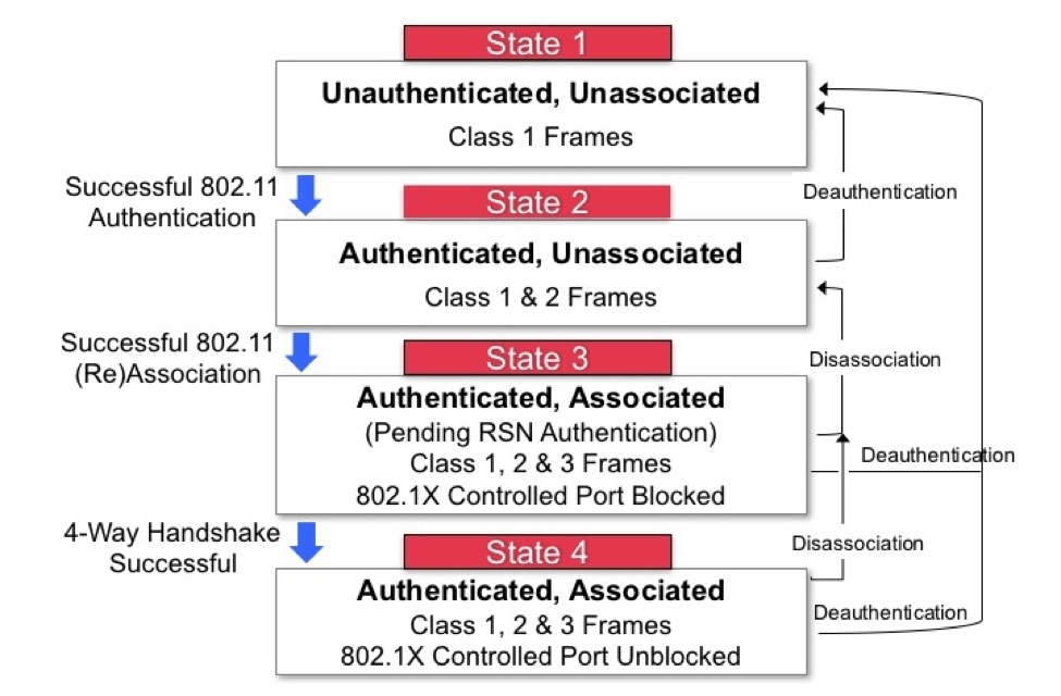
802.11 State Machine
This is where we get into the four states of client connectivity. 802.11 management frame communications are used between a client station and an AP as a client transitions between the four states toward established L2 connectivity. If no security is present then only 3 states are needed.
- State 1 – initial start state, unauthenticated and unassociated
- State 2 – authenticated, not associated
- State 3 – authenticated and associated (pending RSN authentication)
- State 4 – authenticated and associated
If you take a look at the diagram below, you can see the process visualized. I am a visual learner and charts make me happy!
Management Frames:
Management frames are used by stations to join and leave the BSS. They are also equivalent to Management MAC protocol Data Unit (MMPDU). We mentioned subtypes previously and here is a good reason for their existence. Within Management Frames we have 14 subtypes:
- Association Request
- Association Response
- Reassociation Request
- Reassociation Response
- Probe Request
- Probe Response
- Beacon
- Announcement traffic indication message (ATIM)
- Disassociation
- Authentication
- Deauthentication
- Action
- Action No ACK
- Timing Advertisement
Let’s dig into some of the more common:
Beacon:
- AP of a BSS broadcasts the beacons while the clients listen for the beacon frames
- Clients only transmit beacons as part of an IBSS
- Beacons contain timestamps ensuring clients are synced with the AP, as timing for sending is so critical
Passive Scanning:
- Client station listens for the beacon frames that are continuously being sent by the APs
- Typically beacons are sent 10 time a second.
- Provides an initial means for a client to learn about all the BSS capabilities that the AP supports.
Active Scanning:
- Client station transmits management frames know as probe requests. The probe requests frame also contains information about the client station capabilities that can initially be shared with an AP.
Authentication:
This is the first of two steps to connect to the 802.11 basic service set. 802.11 authentication merely establishes an initial connection between the client and the AP, basically ensuring they are both valid 802.11 devices.
Open Sytem Authentication:
Providing authentication without performing any type of client verification, Open System Authentication is considered a null authentication. It is used in conjunction with more advanced network security authentication methods, such as PSK and 802.1X/EAP.
Association:
When a client associates, it becomes a member of a BSS and has established L2 connectivity with the AP.
Basic and Supported Rates:
- Required rates are basic rates
- AP will transmit all management frames at teh lowest configured basic rate
- Data frames can be transmitted at much higher supported data rates.
- If the client station is not capable of communicating with all of the basic rates, the lient station will not be able to associate with the AP and will not be able to join the BSS
- The supported rates are data rates that the AP offers to a client station, but the client station does not have to support them all.
Reassociation:
Reassociation is when a client decides to roam to a new AP, in which it sends a reassociation request frame to the new AP. It is used to transition from one BSS to another BSS. In the end this is basically a roaming request.
Disassociation:
A disassoction is a notification, not a request. Either the client or AP will send a disassociation frame and is a polite way of terminating the association and will include a reason code as to why.
Deauthentication:
Like disassociation, this is also a notification, not a request. Additionally the client or the AP can send a deathorization request. Deauthentication will automatically cause disassociation. If sent by an AP the client is sent back to state 1 of the 802.11 state machine. Last, it carries a reason code as to why the deauthentication occurred.
Action Frame:
An action frame is a type of management frame used to trigger specific actions in a BSS. It can be sent by clients or APs. Within an action frame there are three sections:
- Category: describes an action frame
- Action: action to perform
- Elements: adds additional information specific to action
Examples: Channel switch announcement, transmit power control, and neighbor report requests.
Control Frames:
Control frames assist with delivery of data frames and are transmitted at one of the basic rates. It is also used to clear the channel, acquire the channel, and provide unicast frame acknowledgments. Additionally it has a MAC header and trailer, but no frame body.
Most common Control Frames:
ACK Frame:
An ACK frame allows for a station to know that a frame it transmitted was properly received. It is for the receiving station to notify with an ACK. Every unicast frame must be followed by an ACK.
Block acknowledgement
Block Acknowledgment improves channel efficiency by aggregating several acknowledgments into one single ACK frame. There are two types:
- Immediate Block ACK for low latency traffic
- Delayed Block ACK for latency-tolerant traffic
PS-Poll:
When legacy power management is in use, the PS-Poll frame is an 802.11 control frame used by client stations to request an AP sends buffered traffic for the client station. PS-Poll uses Duration/ID to identify itself to AP using Associated ID (AID).
RTS/CTS:
RTS/CTS is the mechanism that performs a NAV distribution and helps prevent collisions from occuring. NAV distribution reserves the medium prior to the trasmission of teh data frame. Every time the station wants to transmit a frame it must perform a RTS/CTS exchange prior to the normal data transmissions.
CTS-To-Self:
Used as a protection mechanism CTS-To-Self is used when different technologies, such as 802.11b/g/n coexist in the same BSS. Higher throughput than RTS/CTS is achieved by sending four frames. It is better suited for use by an AP as opposed to client stations.
Protection Mechanisms:
The client sends out RTS/CTS to AP in a data rate and modulation all other clients can understand, or by transmitting a CTS-To-Self the same way. Listening stations will then look at the Duration/ID value and set their NAV timers accordingly. Once reserved, the transmitting station sends in a modulation that is its standard. An ERP protection mechanism is used so that legacy 802.11b and 802.11g clients can co-exist in the same BSS by using the RTS-CTS or CTS-To-Self protection mechanism.
Data Frames:
Most data frames carry the actual data that is passed down from the higher layer protocols. Layer 3-7 MSDU payload is normally encrypted, but not always if a layer 3-7 payload does not exist. Two of the most common data frames are data and QOS dat. Although 15 subtypes exist, there are only four to be concerned with.
- Data
- Null
- QOS Data
- QOS Null (no data)
QOS and Non-QOS Data Frames:
As we have discussed previously QOS mechanisms are required for WMM. Most modern day radios are considered to be QOS stations, which makes most enterprise deployments to be QBSS (QOS Basic Service Set).
Non-Data Carrying Frames:
Some 802.11 data frames don’t carry data of which Null and QOS Null frames are examples. They have a header but now body. Clients use a Null function frame to inform the AP of changes in power-save status by changing the Power Management bit.
Power Management:
In Power Management, the two legacy power-management modes supported by the 802.11 standard are active and power-save mode.
- Active mode: Station is always ready to send or receive and provides no battery conservation
- Power-save mode: Client will shut down some of its transceivers components for a period of time to conserve power.
Traffic Indication Map:
The TIM field is a list of all stations that have undelivered data buffered on the AP, waiting to be delivered.
Delivery Traffic Indication Map:
The DTIM is used to ensure that all stations using power management are awake when multicast or broadcast traffic is sent.
WMM-Power Save and U-APSD:
WMM-Power Save (WMM-PS) certification is based on U-APSD (Unscheduled automatic power save delivery). WMM-PS is designed to have clients spend more time in a doze state and consume less power as well as minimize latency for time sensitive applications like voice during the power-management process. WMM-PS uses a trigger mechanism to receive buffered unicast traffic based on WMM access categories. To use WMM-PS, both the AP and client must be certified.
Chapter Review
Our most recent chapter reviews have been very heavy on technical content which has lead the blog content to be a bit dry, but necessary to cover the required content. As things open up a bit more with MIMO and WLAN Architecture on deck, I think the content will be a bit more conversational.
In this chapter we discussed all things 802.11 MAC. We went over the MAC Header and frame body, 802.11 addressing, 802.11 State Machine, Management frames, Action frames, Control Frames and much more. To ensure you are driving home a lot of this content I would recommend drawing out the processes a few times and see if you can commit the processes to memory. This worked well for me when it came to how the information flows through the Data-Link and Physical Layers. This weekend I will be reading up on MIMO and hope to have another post out by Monday.


