CWNA Chapter 8: Medium Access
Here we are with the next installment of CWNA Chapter review. It has been about a week since I posted here. So you might be wondering what happened. Have I succumbed to the fate of some bloggers, in which they get excited at first and then fall off the map, leaving a blog to collect dust? Fortunately, that is not the case. I have felt slightly scattered with the recent events in the United States. I have had some projects at work that have been keeping me busy. If I look back at the time I had available to me and ask myself if I could have made use of it. I could have 100%. I did not and that is on me. It was a lack of focus I am trying to overcome. Maybe my brain was telling me I needed a break. Either way, thanks for standing by. Let us put the train back on the track.

To Avoid or Detect Collisions, That is the Question
Carrier Sense Multiple Access with Collision Detection CSMA/CD or Carrier Sense Multiple Access with Collision Avoidance CSMA/CA? I will no longer subject you to reading either of those without using the acronym. I’m sorry! What are they? Well, they are ways for stations to contend for access to the medium, 802.3 ethernet uses CSMA/CD while wireless uses CSMA/CA. So what are the differences between the two, they sound really similar? CSMA/CD is used for 802.3 ethernet and the client stations must wait and listen to see if another device is transmitting , otherwise the station has to wait until the medium is available. CSMA/CA does this as well, but differs on what happens when no other stations are transmitting.
CSMA/CD Process
- Check to see if another node is transmitting
- If not, the node sends the first bit of info
- Then if no collision occurred, the node continues to send the other bits while continuing to monitor whether a collision has been detected
- If a collision is detected, the wired node calculates a random amount of time to wait before starting the process again
- Wireless radios are not capable of transmitting and receiving at the same time, hence no collision detection
CSMA/CA Process
- When a station has determined no other stations are transmitting the 802.11 radio will chose a random backoff value
- Then the station waits an additional period of time, based on that value before transmitting
- While it waits, it monitors to make sure no other stations start transmitting
- Due to the wireless being half-duplex, it is important only one 802.11 radio has the medium at a time
- Collisions can still occur
Collision Detection in Wireless
Every time an 802.11 radio transmits a unicast frame, assuming the frame is received properly, the 802.11 radio that received it will reply with an ACK frame. 802.11n and 802.11ac are unique in that they can make use of frame aggregation, which groups multiple unicast frames together. A Block ACK is the delivery of aggregated frames. Important to note is broadcast and multicast frames do not require an acknowledgement. If a frame is corrupted, the CRC fails, and no ACK will be received from the receiving radio, causing the transmitting radio to retransmit.
Distributed Coordination Function (DCF)
Distributed Coordination Function is the fundamental access method of 802.11 communications, and the CSMA/CA process is the foundation of the DCF.
It has four main components:
- Physical Carrier Sense
- Virtual Carrier Sense
- Pseudo-random backoff timer
- Interframe Spaces
Let’s get into what they do and why they are important!
Physical Carrier Sense
Physical Carrier Sense is a mechanism used to determine if the radio frequency medium is busy. It is performed constantly by all stations that are not transmitting or receiving. There are two purposes that make up physical carrier sense. First, is to determine whether a frame transmission is inbound for a station to receive. If the medium is busy, the radio will attempt to synchronize with the transmission. Second, it needs to determine if the medium is busy before transmitting. It must be clear before a client can transmit.
To achieve the above goals, a clear channel assessment (CCA) is used which involves listening for RF transmissions at the PHY layer. There are two CCA thresholds that are used with listening to the RF medium. Starting with Signal Detect (SD), it is used to identify any 802.11 preamble transmissions from another transmitting 802.11 radio. The threshold is statistically around 4db SNR for most radios to detect and decode an 802.11 preamble. Next we have Energy Detect (ED), which is used to detect any other type of RF transmissions during the CCA. The threshold for ED is 20db higher than SD.
Virtual Carrier Sense
Virtual Carrier Sense uses a timer mechanism known as the network allocation vector (NAV). The NAV timer maintains a prediction of future traffic on the medium based on duration value information seen in a previous frame transmission. When a listening radio hears a gram transmission from another station, it looks at the header of the frame and determines whether the dDuration/ID field contains a Duration Value or ID value. If it is set to Duration Value, the listening station will set its NAV timer to this value.
When a client transmits a unicast frame, the Duration/ID Field contains a value from 0-32,767. This value represents the time in microseconds that is required to transmit an active frame exchange process so that other radios do not interrupt the process. The value of the Duration/ID Field indicates how long the RF medium will be busy during a frame exchange, before another station can contend for the medium.
A station cannot contend for the medium until its NAV timer is 0, nor can a station transmit on the medium if the NAV timer is set to a non-zero value. Virtual Carrier Sense is a layer 2 carrier sense mechanism.
Pseudo-random backoff timer
An 802.11 station may contend for the medium during a window of time known as the backoff time. The station selects a random backoff value using a pseudo-random backoff algorithm, then chooses a random number from a a range called a contention window (CW) value. This triggers the pseudo-random backoff timer. Next there is a countdown based on ticks of a clock which are called slots. Once zero is reached, the station reassess the channel and if it is clear, transmissions begin.
Interframe Space
Interframe Space is a period of time that exists between transmissions of wireless frames. There are 10 types of which we have a partial list below. SIFS and DIFS are the two most common.
- Reduced interframe space (RIFS) – highest priority
- Short interframe space (SIFS) – second highest priority
- PCF interframe space (PIFS) – middle priority
- DCF interframe space (DIFS) – lowest priority
- Arbitration interframe space (AIFS) – used by QOS stations
- Extended interframe space (EIFS) – used after receipt of corrupted frames
Point Coordination Function
Point Coordination Function is a medium access method. The access point performs the function of the point coordinator (PC). This will only work in a BSS. Additionally it cannot be used in an ad-hoc network as no AP exists in an IBSS. PCF is a form of polling and because polling is performed from a central device, PCF provides managed access to the medium. In order for this to work the AP and station must support it. The AP will alternate between PCF and DCF mode. While in PCF mode, that time is known as the contention-free period, in which the AP polls only clients in PCF mode. It is a method of prioritizing clients. While the AP is in DCF mode, it is known as the contention period (CP). At this point PCF is considered obsolete.
Hybrid Coordination Function:
As an enhancement to DCF and PCF, HCF combines capabilities from both and adds enhancements to them to create two channel access methods, Enhanced Distributed Channel Access (EDCA) and HCF Controlled Channel Access (HCCA). Unlike DCF and PCF, where an 802.11 radio is allowed to send a single frame, HCF allows multiple frames to be sent. When an HCF compliant radio contends for the medium, it receives an allotted amount of time to send frames called a transmit opportunity (TXOP). During this TXOP time, the 802.11 radio may send multiple frames called a frame burst. A SIFS short interframe space is used between each frame to ensure no other radios transmit during the frame burst.
enhanced distributed channel access
This wireless medium access method provides differenctiated access that directs traffic to four access-catagory QOS priority queues. The four categories should be be familiar to you if you are already familiar with QOS. They are in order of highest priority to lowest, Voice, Video, Best Effort, and Background.
WiFi Multimedia
WMM is based on EDCA mechanisms. 802.1D priority tags are from the ethernet side are used to direct traffic to four access-category priority queues mentioned above.
- WMM Voice Priority – Highest, allows multiple concurrent VOIP calls.
- WMM Video Priority – Supports prioritized video traffic before other data traffic.
- WMM Best Effort – Traffic from apps or devices that cannot provide QOS capabilities.
- WMM Background – Low priority like print jobs and file transfers
WMM prioritizes different classes of traffic during the contention process as you will see in the backoff times listed below.
- Voice – 2 SIFS slots plus 0-3 slots
- Video – 2 SIFS slots plus 0-7 slots
- Best Effort – 3 SIFS slots plus 0-15 slots
- Background – 7 SIFS slots plus 0-15 slots
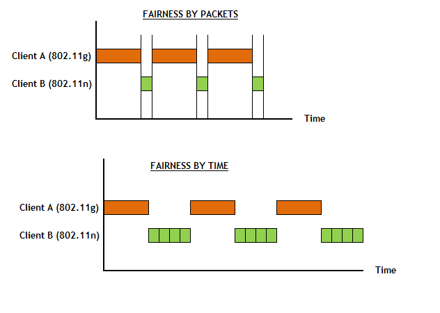
Airtime Fairness
I found Airtime Fairness to be the most interesting part of this chapter. From what I understand, this is not a standard and not all vendors support it, and if they do it is propriety in its implementation. So what is airtime fairness? Basically it is the ability to offer higher data rate devices the same amount of time on the medium as a slower data rate, allowing for more data to be sent in the same period of time. Without the implementation of airtime fairness, you had equal opportunity to the medium as opposed to equal time. With equal opportunity you were given the same number of times to access the medium. With equal time, higher data rate devices can send more packets in the given time and get on and off the medium quicker. In the diagram below you can see where fairness by packets or equal opportunity allows a packet by a slower data rate device to complete, then the higher data rate device sends. This process continues until completion. With fairness by time or equal time, the slower data rate devices send for the same amount of time with each turn but only send one packet, where the higher data rate device is sending 4 packets per turn.
The following video by Tom Carpenter from CWNP is an excellent resource for this entire chapter. I would highly recommend watching it.
Chapter Review
In the previous CWNA chapter 7 Review we discussed the wireless topologies and built upon that here. CWNA chapter 8, allowed us to explore CSMA/CD and CSMA/CA, Distributed Coordination Function, Point Coordination Function, Hybrid Coordination Function WiFi Multimedia and Airtime Fairness. All of these items relate to how our stations acquire access to the wireless medium and the various ways we can prioritize that traffic.


