RF and Audio
Are you ready? Get ready…..it’s RF Basics time. But we are going to put a different spin on it. We ARE going to hit the basics, but with the added comparison to car audio thrown in. Why the heck would you do that? Well, in a previous life, I spent almost 20 years in the 12 volt electronics business. Remember the first post HERE. Using car audio will help explain RF basics a bit better.
RF, Your so Basic
It is time to talk RF basics. Unlike a lot of other areas that are a bit foreign to me, this isn’t one of them. I spent years working on sound quality installations in the car audio industry, tuning audio systems using Digital Signal Processing, which uses time delays (think like multipath adjustments), frequency crossovers (audio frequency filters), and equalization (adjusting frequency amplitude).
To get started we need to talk about how wireless signal travels. It is considered an unbounded medium, meaning that the signal is not contained and radiates in all directions, unless influenced by an outside force. More on that later when we discuss reflection, refraction, diffraction, scattering and attenuation.
Wavelength
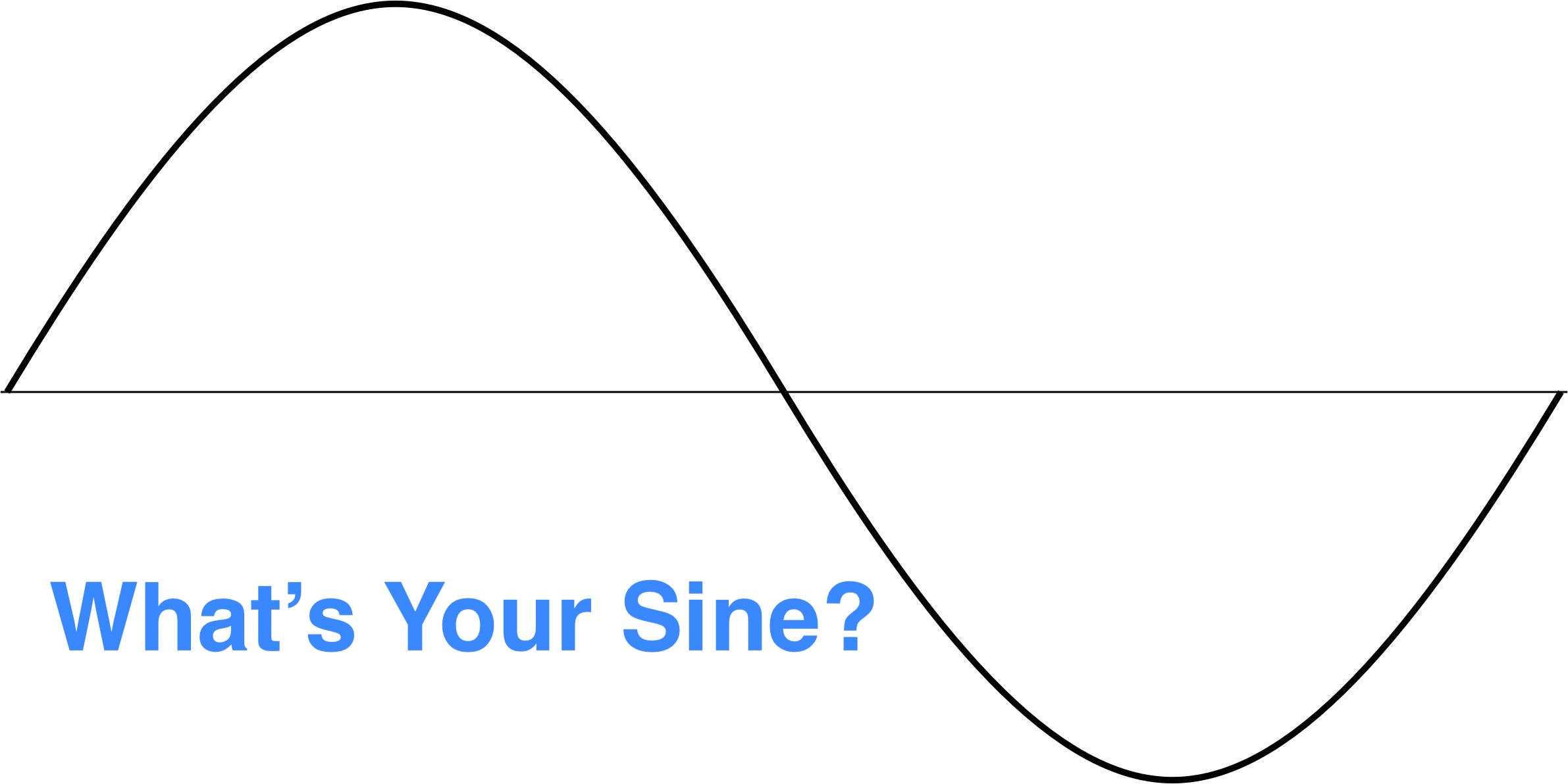
Wavelength is an alternating current that changes between negative and positive voltage continuously. It is measured by taking the distance between two successive crests of the sine wave seen below.

To complete a wave it the signal needs to travel 360 degrees, so the middle line above is 0 degrees, the first peak is 90 degrees, the bottom trough is 270 degrees and back to the middle is 360 degrees, thus completing the wave. The length of the wave determines the width. Higher frequencies will pull the peaks closer together and lower frequencies will make it wider. When you listen to music, the bass is your lower frequencies and the high pitched sounds are high frequencies. The frequency range you car hear as a human is different person to person, but generally it is from 20Hz to 20,000Hz. RF in 2.4GHz and 5GHz is 2.4 billion Hz and 5 billion Hz respectively. Think of the difference between 20Hz (20 cycles per second) to 5GHz (5 billion cycles per second). Fun fact, although you can’t hear below 20Hz, you can still feel it.
Frequency
We talked a bit about frequency already, and there is a good reason for that. You can’t have wavelength without frequency and vice versa. Frequency is the amount of times a specified event occurs. In this case how many times a wave cycles per second. The typical measurement of frequency is in hertz (Hz).
Amplitude
If you look at the height of a wave, we are looking at its amplitude. If you were to listen to a single note in the car and then turned the volume up, you would effectively be increasing the amplitude. The frequency wouldn’t change nor would the wavelength. The only thing that would change would be the height of the wave, all other things remaining equal. The main reason for buying a car audio amplifier is to increase the effective height of all the frequencies wave height all while keeping the sine wave clean. It goes a bit deeper than that, but for simplicities sake, it will suffice. To further expound on amplification, we need to talk about what affects it. As a signal passes through an object, it becomes attenuated which will decrease the overall amplification or signal strength. We take into account that the initial signal sent is called transmit amplitude and the received signal is called, you guessed it, received amplitude. Amplification can also be affected by cables and connectors which will add some perceived resistance to the connection.
Phase
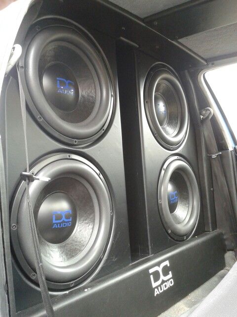
Do you want to destroy a good signal, then make sure it is 180 degrees out of phase. We get into this a bit later but that is called nulling in the RF world and “you wired it wrong” in the car audio world. Phase is measured in distance, time or degrees. When the peak of two different signals are the same that share the same frequency they are considered in phase. Here comes the car audio analogy! If you have ever had a pair of subwoofers in your car…..bass speakers….the ones you hear rattling the trunk of the car next to you at a stop light, then you can follow me here. So speakers have voice coils (we will assume one per speaker for this example) in which they have one positive and one negative connection. If you hook the speaker wire up correctly the positive output from the amplifier goes to the positive on the speaker and the negative to the negative. Seems simple, and it is, but not always. If by chance you connect positive and negative correctly on one speaker and backwards on the other your output will be dramatically reduced to almost nothing. The speakers are now 180 degrees out of phase, cancelling each other out.
Check out the video below for a great visual explanation of frequency, phase, and amplitude.
RF Frequency Characteristics
Absorption
When a signal passed through an object an amount of absorption happens. The signal is attenuated by a certain amount of db depending on the material. A sheetrock wall for instance will have less absorption than a concrete wall.
Reflection
Yes, this is what happens when you look in a mirror! Now stop being vain and pay attention! In the RF world reflection is when a signal bounces off an object such as glass, metal, doors and walls. This typically happens with smooth surfaces causing the signal to bounce off at the equal angle to which it arrived. When reflection happens it can lead to multipath issues which can degrade signal. Multipath will be covered later on.
Scattering
Scattering is caused when RF signals hit an uneven surface and is reflected into multiple sections. The most common explanation here is shining a flashlight onto a disco ball. There are many mirrors on the ball, take the single beam of light and scattering it all around the room.
Refraction
As RF signal travels, it sometimes comes in contact with something it has to go through like air temperature changes, water vapor, and changes in air pressure. This causes the RF to bend and it passes through these variables.
Attenuation
Attenuation brings us full circle, as it is what happens due to our previous scenarios of absorption, reflection, scattering and refraction. It is simply the decrease in amplitude or signal strength.
Free Space Path Loss
As RF signals travel, they degrade due to the natural broadening of the waves, referred to as beam divergence.
So Many Paths
In this next section we talk briefly about Multipath which is when two or more signal paths are being received at the receiving antenna at the same time or with nanoseconds of each other,. This is due to reflections, refractions, scattering and diffraction. The difference between the paths is know as delay spread.
Within multipath there are a few factors to understand.
- Upfade – Not all forms of multipath are bad. In this case upfade is when the signals are received at or near the same time cause an increase in amplitude.
- Downfade – This is a destructive from of multipath in which the signals arrive at the same time, but due to delay on one of them they are out of phase, decreasing amplitude.
- Nulling – When you hear of a signal being 180 degrees out of phase resulting in cancellation, that is nulling.
- Data Corruption – If you encounter a delay that causes bits to overlap, you will wind up with data corruption. This difference in time is know as delay spread, which results in decreased amplitude. This is also known as intersymbol interference. Fortunately we have CRC (Cyclic Redundancy Check) that will detect these errors.
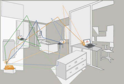
If you take a look at the picture below, which is from this Document from the IEEE on MIMO, you can see the way different signals can leave the station and arrive at the receiver.
Gain – The last item from chapter three that we need to discuss is gain. Gain is the increase in amplitude or signal strength. There are two types of gain, active and passive.
- Active Gain – this is caused by a transceiver or amplifier
- Passive gain – this is caused by focusing RF energy by using and antenna
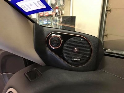
Back to Car Audio
So I kind of trailed off on the car audio talk for a bit to finish off this post with a correlation of all the relevant items at once. About 15 years ago I competed in car audio SPL competitions. SPL stands for Sound Pressure Level. The idea was to make the car as loud as possible on the inside. You had a couple of things you needed to have happen to achieve this. Obviously, you needed to create pressure in the car. You did this by putting large diameter subwoofers in a fairly large enclosure. More surface area, meant you could push more air, more pushed air, more pressure. That’s great, what does that have to do with RF. Here is where it all comes into play. We know we have a sine wave, and at the top of the wave is its peak. Waves travel over distance based on their frequency. The peak of the wave is where the most amplitude happens. That being said we would build our speaker wall and move it backward and forward in the vehicle trying to get the frequency that was the loudest in the car (resonant frequency) to the peak of its wave at the dashboard, where the measurements were taken. We were working with frequencies around 50Hz so completing the wave within a car environment was next to impossible, but finding the highest part of the wave form was not. So now we have equated wavelength and frequency, what about phase. Most SPL competition vehicles had multiple speakers, so ensuring they were all wired properly was of paramount importance. Even if you had a wall of twelve speakers and one was wired out of phase it would be catastrophic for the output levels. When it came to amplitude, we typically had multiple amplifiers running many speakers. This effectively allowed us to increase the possible height of our wave.
Moving away from the SPL scene and into the high end sound quality realm we start to concentrate on things like absorption, reflection, and phase. In a high end audio system, whether it be for car or home, you ideally want a dead space to play audio. You will see recording studios with the angled foam walls. This is for absorption and reflection. In their case they are using it for an advantage, where in RF this is typically a bad thing. There are cases where you will try to place an AP in a location in which you use a wall or walls to attenuate the signal naturally which in my opinion is good design if needed. In the car environment we do the same thing, by adding sound deadening material throughout the interior to absorb vibration, thereby helping overcome road noise. Another ideal scenario is to have the audio from the left and right speaker meet your ear at the same time. In a car you are positioned either left or right, never middle. So a couple things we can do here. We can try to aim the speakers at the opposing windows and use reflection. This equalizes the length of the signal which decreases the difference to your ears. The only other way to do this is to push the speakers further away from you. Additionally we can use digital signal processing to delay the audio from the closer speaker to allow the opposite signal to reach you at the same time which I would relate to what MIMO does with multipath. There are a ton more comparisons I could make but we will finish up here.
End of Chapter Review
Today we reviewed RF characteristics and behaviors, using car audio to help drive home the concepts. This chapter really hits home on the basics of RF signals and how they are affected by the environment in which they interact. We learned what impacts our signal in both good and bad ways. Last, we learned in what ways gain is achieved. A good wireless engineer will be able to use all of this information to better their overall design by using these characteristics to their advantage. As always, let me know what feedback you have on the content provided. I am interested to know if you found the car audio comparison useful.


