WLAN Design Concepts
I have been ready for this chapter for awhile. As someone who does WiFi Design and surveying as part of my role, I really get into learning about how improve upon what I already know. About two years ago I went through Ekahau ECSE training (taught by Sam Clements), completed the class, and then updated to the new ECSE Design certification when it was released. I truly enjoy WLAN Design and all of the intricacies required for a successful design.
WLAN Coverage Design
As we get into how to create a proper WLAN Design, we need to keep in mind that we should be doing so from the clients perspective. If the client does not support technologies we are implementing, then we have wasted precious time spinning our wheels for no gain. That being said, when doing designs, it is always a good idea to find out from you clients if they will be adding new devices soon, so we can prepare for that.
Received Signal
When it comes to received signal, the lowest RSSI would would aim for would be -70dBm. If we were to be designing for VoWiFi we would want to bump that up to -65dBm. More on that later.
Signal to Noise Ratio
Let’s keep in mind that SNR is the difference between the noise floor and the received signal. If RSSI is -65dBm and the noise floor is -90dBm then SNR is 25dB, which is considered great. If your SNR is poor then data corrupmtion can occur, resulting in L2 retransmissions. A minimum of 20dB SNR is recommended unless VoWiFi is being used in which 25dB is appropriate. The higher the SNR, the higher your MCS rate will be. 802.11ac clients will require an SNR of 29dB in order to reach 256 QAM and for 802.11ax clients, an SNR of 35dB would be required to maintain 1024 QAM.
Dynamic Rate Switching
When a client radio moves away from an AP, they will shift down to lower bandwidth capabilitites using a process know as DRS (dynamic rate switching). This is ever changing depending on the clients distance to the AP. The further away the client gets, the lower the rates go, closer and they increase. When we shift to lower data rates, this means our coverage area is expaning as our data rates decrease. For most vendors DRS capabilities are based on RSSI, packer error rates, and retransmissions. This is proprietary from vendor to vendor. DRS can be initiated from AP or client.
Transmit Power
APs deployed with max power, will result in oversized coverage cells, and not meet capacity needs in most instances. This also will result in an increased likelyhood of co-channel interference. Additionally, sticky clients can become an issue. The recommendation would be to set your APs to 1/4 to 1/3 power. High density deployments may require more APs at lower power levels to keep the cell sizes as small as possible.
Roaming Design
Roaming is the method by which client stations move between RF coverage cells in a seamless manner. Client stations decide when to roam, not the AP. The WLC may be involved in the decision, but in the end the client initiates the roaming process with a reassociation request frame. Roaming thresholds are usually decided using RSSI, SNR and bit-error rate. As with DRS, roaming is also vendor specific in regards to when the client initiates a roam. In 802.11k, the use of RRM and neighbor reports were defined to enhance roaming performance. 802.11r defined faster secure handoffs when roaming occurs between cells in a WLAN using the strong security defined in a RSN. 802.11v added AP capacity load to the factors taken into account. For voice, Voice-Enterprise certification from the WiFi Alliance ensures that 802.11k, 802.11r and 802.11v are supported on the client side.
Primary and Secondary Coverage
Most vendors suggest a design in which you have 15-30 percent cell overlap. This is difficult to measure as cells are irregulary shaped due to attenuation brought on by the environment. Ideally you should make sure the client always has duplicate coverage from multiple access points. You want to hear one AP a a specific RSSI and another AP at a slightly lower RSSI. In this example, your primary cell would be -70dBm and your secondary would be at -75dBm. If full redundancy is important, you will need to ensure that both your primary and secondary RSSI are the same.
Layer 3 Roaming
Layer 3 roaming poses a problem when a client roams to an AP with a different vlan and subnet. The client will be required to obtain a new IP, thus losing connectivity briefly. This will impact any connection-oriented applicatoins already running. The only way to get around L3 roaming is to use the Mobile IP standard, a protocol from the IETF. This allows more users to move from one L3 network to another while maintaining the original IP. This uses some form of tunneling and ip header encapsulation to allow packets to traverse between separate L3 domains, with the goal of maintaining upper-layer communication.
Process:
- Mobile clients obtain IP from HA (Home Agent) who is the orginal AP to which it assocaited
- HA shares client MAC/IP table called a home agent (HAT) with another device called the foreign agent (FA).
- The FA handles all Mobile IP communications with teh HA on behalf of the client
- The Foreigh Agents IP address is known as the care-of-address.
- When the client roams, the FA uses the HAT tables to locate the HA of the mobile client
- FA then contacts teh HA and sets up a Mobile IP tunnel.
- All traffic destined for the client is intercepted by the HA and sent through the tunnel to the FA.
- The FA then delivers the tunneled traffic to the client.
Channel Design
Proper channel reuse design is needed to guarantee seamless roaming as well as to prevent two types of interference that are a result of improper channel design.
- Adjacent Channel Interference (ACI): ACI refers to degradation of performace resulting from overlapping frequency space that occurs due to an improper channel reuse design. The 802.11-2016 standard requires 25MHz of space between the center frequencies of 2.4GHz channels to be considered non-overlapping. In the US as you may well know, only channels 1,6 and 11 fit this bill. If ACI does exist, the transmitted frames will become corrupted, the receivers will not send ACKs, and L2 transmissions will increase.
- Co-Channel Interference: When all the APs are sharing a channel, this causes unnecessary medium contention overhead called co-channel interference. The radios are doing exactly what they should be in this case by using CSMA/CD. Avoiding CCI is virtually impossible in 2.4GHz because RF continues to propagate outside the designed cell down to just 4dB above the noise floor. CCI is also know as overlapping basic service set (OBSS). It is important to note that clients cause more CCI than the actual APs do. Turning off 2.4GHz in dual-frequency APs is a good design idea when feasible, relying more on 5GHz.
2.4GHz Channel reuse
With 2.4GHz you will want to attempt to triangulate the 3 channels so you never have channel 1, 6 or 11 next to each other. Keep in mind on multi-floor deployments, you will need to think in 3 dimensions. You don’t want to have an AP on channel 1 right above another AP also on channel 1 a floor below. Never assume floor to floor signal propagation. Always do your due diligence and measure the attenuation with your site survey tool of choice between the floors.
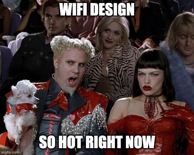
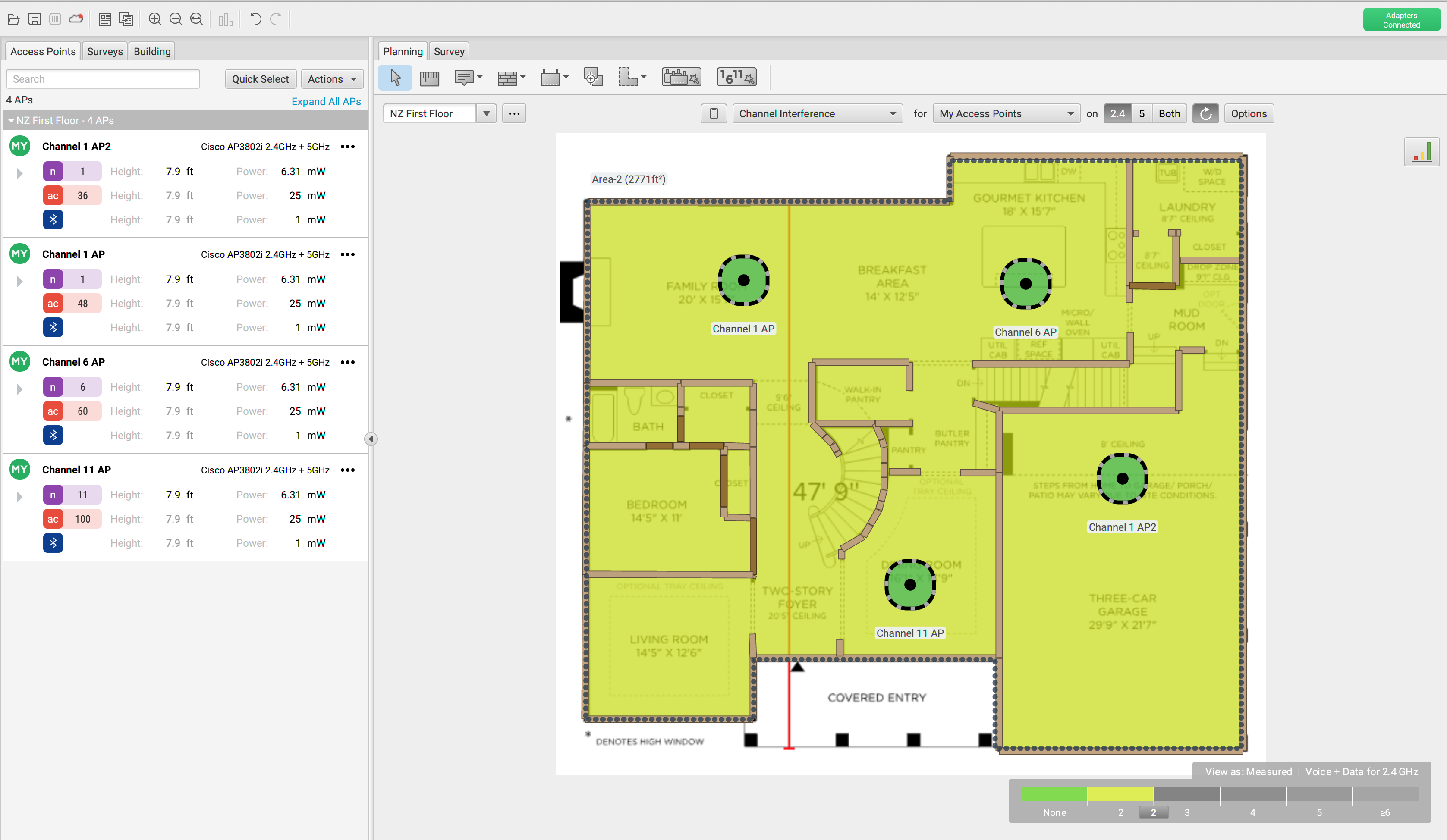
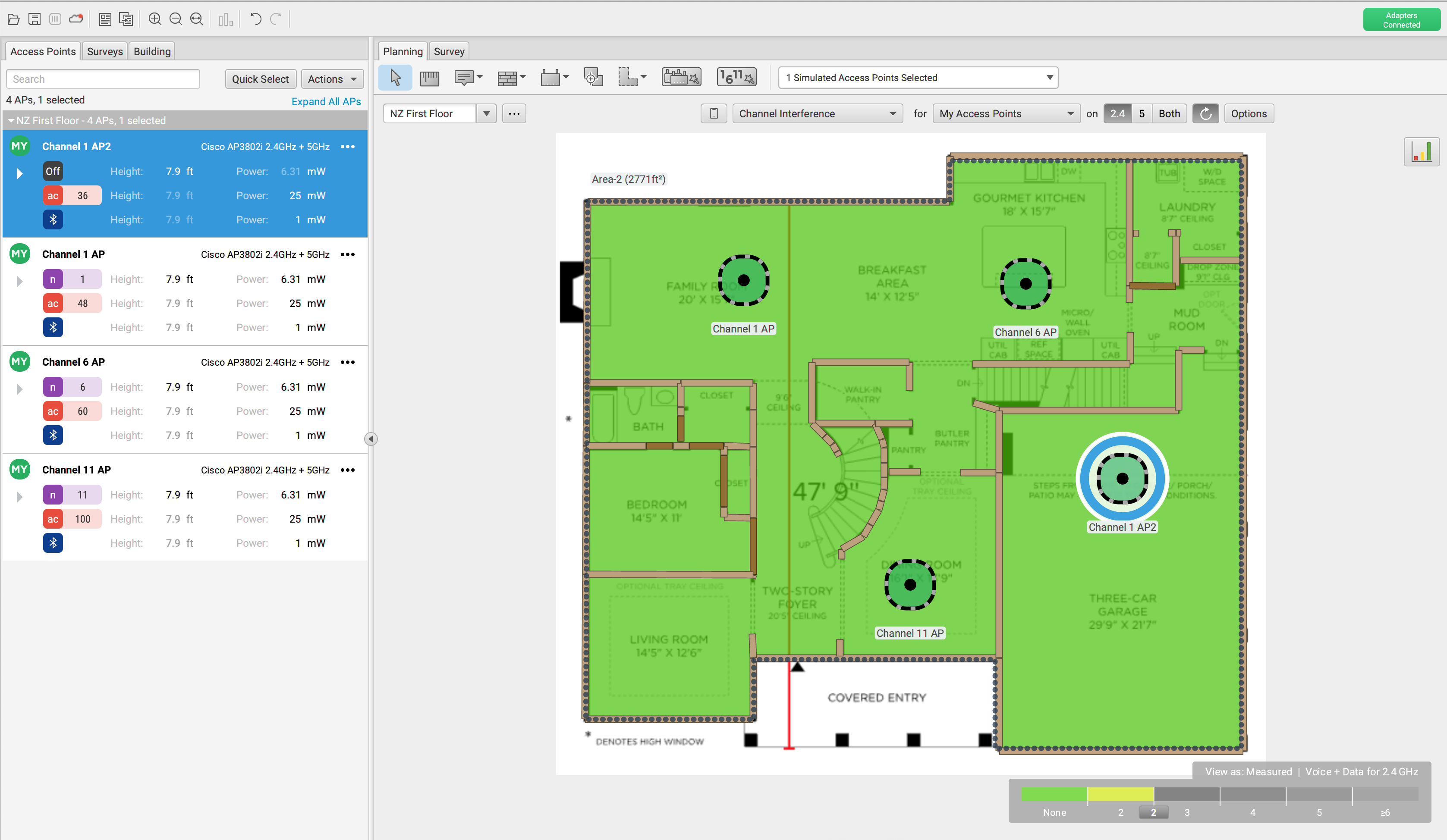
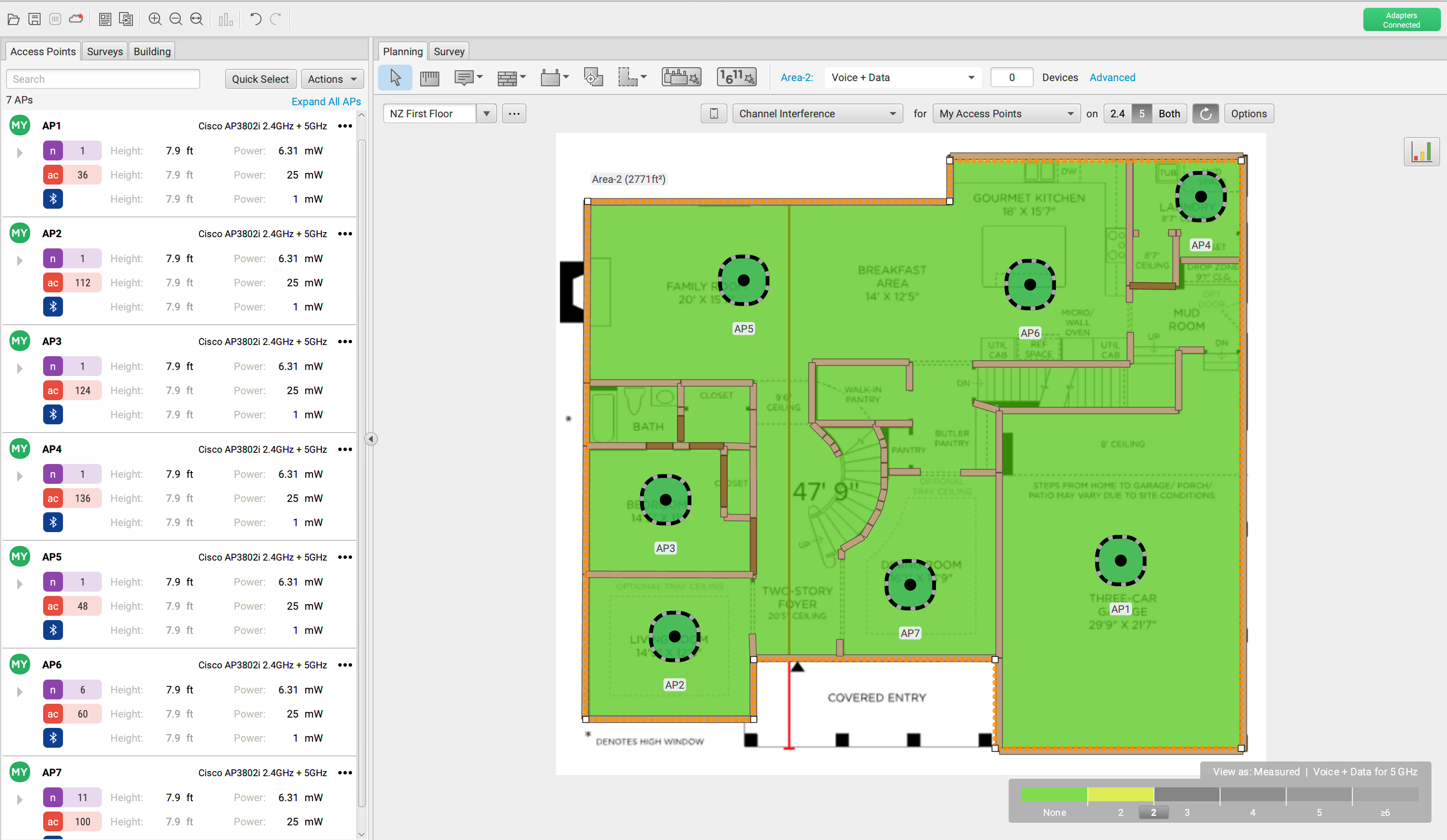
Below is a mock up predictive design I threw together in Ekahau to show what the channel overlap looks like and two ways we can resolve it. Keep in mind this map is the first floor of a single family home and I would not recommend three APs that close together, but it works for the explanation. In the first picture we see the first floor design with four access points. We have two APs on channel 1, one on channel 6 and one on channel 11. Our map is yellow because we are being shown we have 2 access points with CCI due to the two APs on channel 1. We have a couple ways we have learned that we can solve this. First if we truly needed the four APs for proper 5GHz coverage would be to turn off 2.4GHz on one of the APs, which in the second picture is what I did on the Garage AP. The next thing we could do is remove one of the APs altogether assuming our coverage would be sufficient as in picture three.
5GHz Channel Reuse
In the US, 25 channels are typically available in 5GHz. In Europe there are fewer due to licenses needed for U-NII-3 channels. Try to use channels that are two channels apart to avoid sideband overlap. This helps avoid any adjacent channel interference. You will want to use as many channels as possible. More often than not, the use of DFS channels is encouraged. If a specific DFS channel keeps switching you off of it, simply remove it from the available channel list.
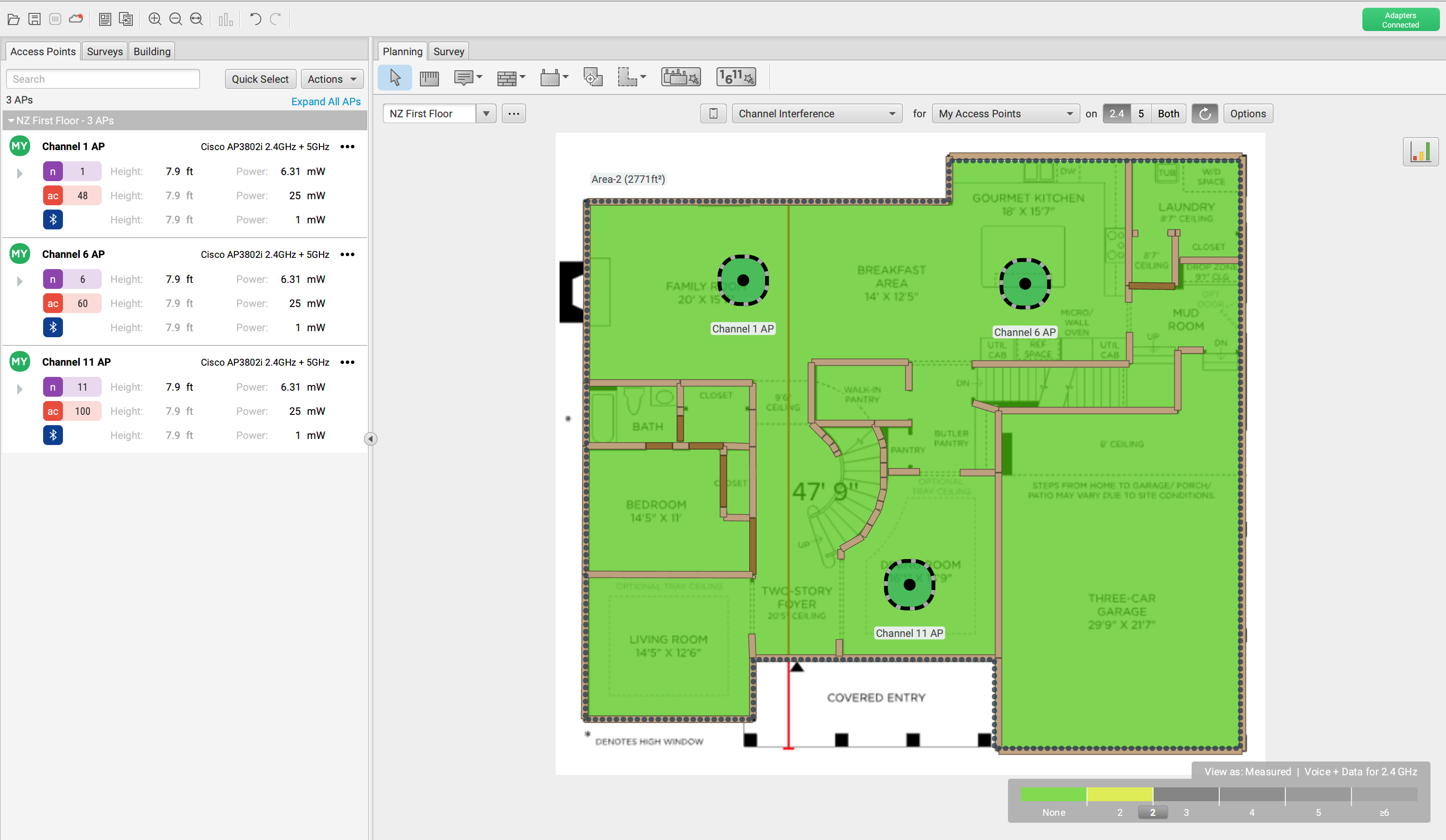
Continuing our representation of a single family home from above, we know that 5GHz allows for a lot more channels and is much easier to channel plan. You will see below that I love to waste money and decided this family needs an AP in every single room on the first floor. But the map is green and there is no CCI being shown…..why? Because 5GHz is awesome with all the available channels we can use! I spread the channels around enough to not introduce CCI even with going very overboard with the AP density.
DFS Channels
All channels in U-NII-2 and U-NII-2e bands are DFS. Typically DFS channels are not enabled on WLAN vendor APs by default. Adding DFS channels to your channel plan allows more channels to help further avoid CCI. Below we will highlight the procedure for DFS use.
- When an AP boots up, it has to listen for 60 seconds if it comes up on a DFS channel. This is before it can transmit.
- If DFS pulses are heard, the AP can’t use the channel and will need to move to another
- If clear, the AP can begin transmitting beacon management frames.
- If on a DFS channel already and a pulse is heard, the AP and associated clients must leave the channel.
- The AP will then send a CSA (channel switch announcement) telling the clients to move to another channel, often channel 36.
- Once moved to a new channel, they cannot go back to the previous DFS channel for 30 minutes.
40MHz Channel Design
When working with 40MHz channels, we have 12 total that are available in 5GHz. If you only used non-DFS channels, then only eight 20MHz or four 40MHz channels are available. With four 40MHz channels, it is likely that contention overhead will exist. This would offset any gains in bandwidth. When you double your channel widths, you are also adding 3dB to your noise floor, thus reducing your SNR. If DFS channels are in use, then 12 total channels in 40MHz are available making contention overhead, much less likely. The clients must support DFS, so that is step one. Multi-floor environments do not scale well with 40MHz unless there is great attenuation between floors. 80 and 160MHz channels don’t scale well in enterprise and should be avoided.
Static Channels and Transmit Power vs. Adaptive RF
Adaptive RF, also know as RRM (Radio Resource Management) provides automatic cell sizing, and automatic monitoring and optimization of the RF environment. RRM is for the most part a proprietary technology for each vendor. Take care not to use RRM as a band aid for poor RF design. A proper RF Survey is still required, or at least a predictive design to assist in creating a good starting point from which to work from. While RRM is generally accepted as a default, static channel and power settings should be used when directional antennas are deployed.
Single Channel Architecture
Single channel architecture is where a WLAN with multiple access points are all transmitting on the same channel and using the same BSSID. From the clients perspective only one AP exists. Uplink and downlink transmissions are coordinated by a WLC. In this case no L2 roaming occurs and all handoffs are done by the WLC. For phones, the zero handoff time is a major advantage as they typically require a 150ms handoff time.
Capacity Design
When designing for capacity, limiting AP power in order to shrink cell sizes is one of the most common ways to meet client capacity needs. High density environments may require APs to transmit at their lowest power settings. Lowering power also helps to alleviate CCI.
High Density
Most environments you will encounter will be considered high density due to each person having multiple devices. In your typical scenario, most people have at least a laptop and a cell phone. In this situation roaming is very important.
Very High Density
Areas where a very large group of people will gather, like auditoriums, gyms and cafeterias are considered very high density. In these environments it is important to note that very little attenuation occurs, meaning CCI will be vitally important to design around. That being said, one way to help deal with this is using directional antennas.
Ultra High Density
Taking it one step further, we enter a space in which there can be tens of thousands of users all in the same space. Some examples of this would be stadiums and other sports arenas.
What Should You Ask When Planning for Capacity
- What type of applications are being used on the WLAN?
- How many users and devices are expected?
- What types of client devices are connecting to the WLAN?
Band Steering
Band steering was developed to try to encourage dual-band clients to connect to a 5GHz radio instead of 2.4GHz. Important to note is that band steering is proprietary and not a product of IEEE. When a client first tries to probe, it will send out on 2.4 and 5GHz. The AP sees that the client is dual band and tries to steer it by only responding in the 5GHz band. If the client persists on 2.4GHz the AP will eventually allow it.
Load Balancing
When a client wants to associate to an AP, the client will send an association request frame to the AP. If the AP is overloaded it will defer the association in hopes the client will try another AP. Over time this should balance clients across APs. In areas where roaming is necessary, load balancing is not a good idea.
Airtime Consumption
CCI is the top cause of airtime consumption and disabling lower data rates on an AP is a great way to help reduce it. Making sure you have good secondary coverage will also help to ensure clients don’t drop down to low data rates. This is all due to management frames being sent at the lowest configured basic rate, which takes up air time at slow data rates. As we have learned, this is expected behavior. Additionally reducing the amount of SSIDs, reduces the amount of beacon frames being transmitted. The recommendation is to have no more than 3-4 SSIDs.
Voice vs. Data
VOIP packets require higher layer IP packet loss to be no greater than two percent. This being said VoWiFi networks need to limit L2 retransmissions to five percent or less. If this criteria is not met then latency and jitter can occur. Best practices dictate that you should design to -65dBm or stronger to ensure the received signal is will above the noise floor as we are aiming for a SNR of 25dB. Data applications can handle a much higher L2 retransmission rate, so adding in VoWiFi after the fact could lead to issues. When at all possible, it is highly recommended to only offer VoWiFi in 5GHz as well as giving it its own SSID.
Dual 5GHz and Software-Defined Radios
SDR (Software Defined Radio) means the radio can function in either 2.4 or 5GHz, so a dual radio AP can offer 2.4GHz and 5GHz or Dual 5GHz. In a situation where dual 5GHz is enabled, you are allowing for more capacity of 5GHz bands. Additionally you will need to make sure you account for channel overlap and that the channels are 60-100MHz apart. Using only 20MHz channels in dual 5GHz is recommended.
Physical Environment
Wall attenuation varies quite a lot. Drywall averages about 3dB, while concrete averages around 12dB of attenuation. For high capacity requirements, using wall attenuation is actually helpful to assist in shrinking cell sizes. Due to the typical omnidirectional nature of most APs, they should not be mounted above 25ft. unless directional antennas are being used. Hallway mounting is to be avoided if possible due to CCI.
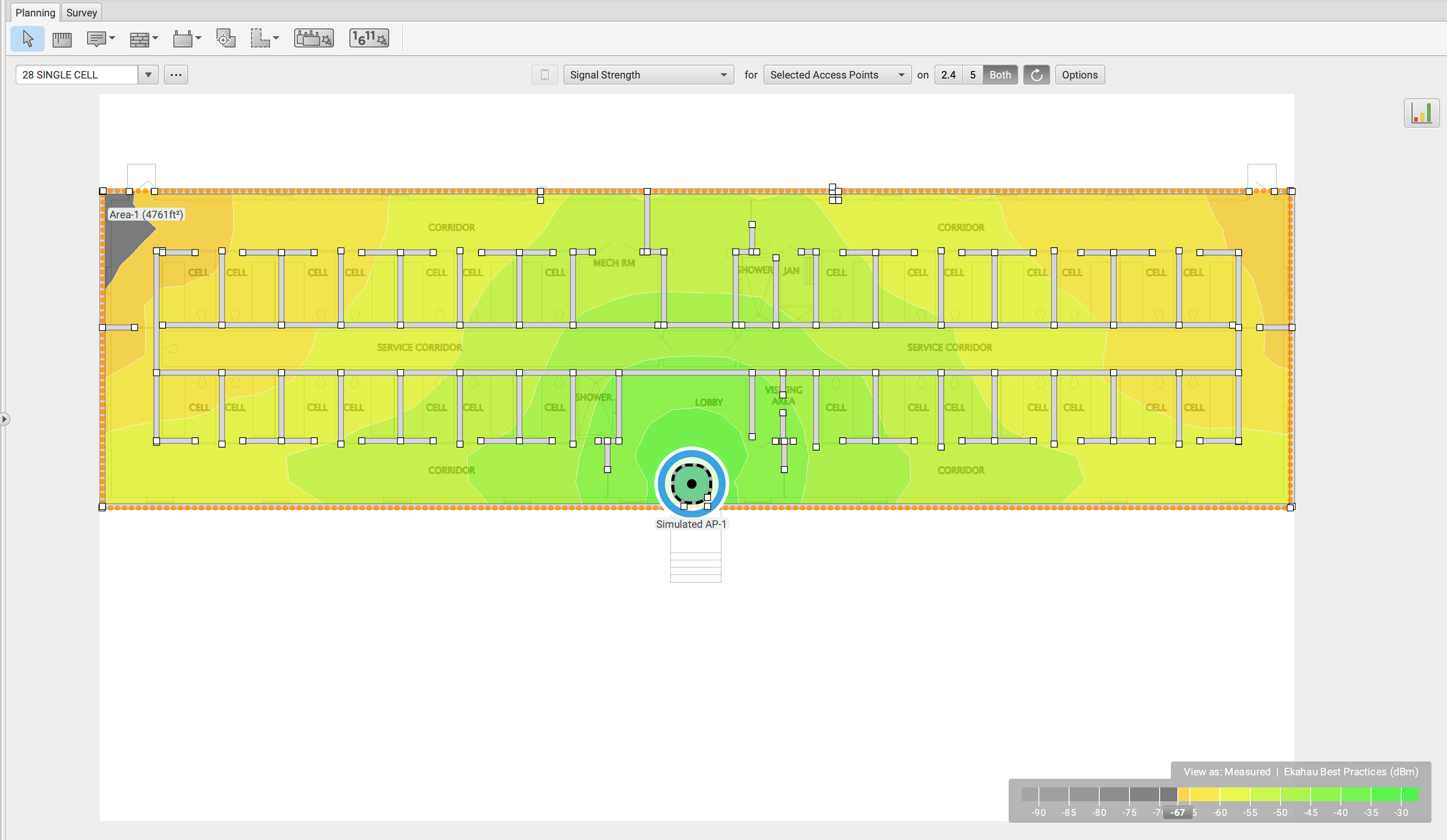
I wanted to show you some examples of how wall types can affect signal propagation using a map of a small prison building consisting of a bunch of cells using a Cisco 3802 as our AP. Keep in mind this is a predictive design and not real world measurements. This example works great as there are a lot of walls to create the attenuation.
In the first picture I changed the wall types to resemble cube space. You can see that this allows the signal from a single AP to cover almost all of the floor.
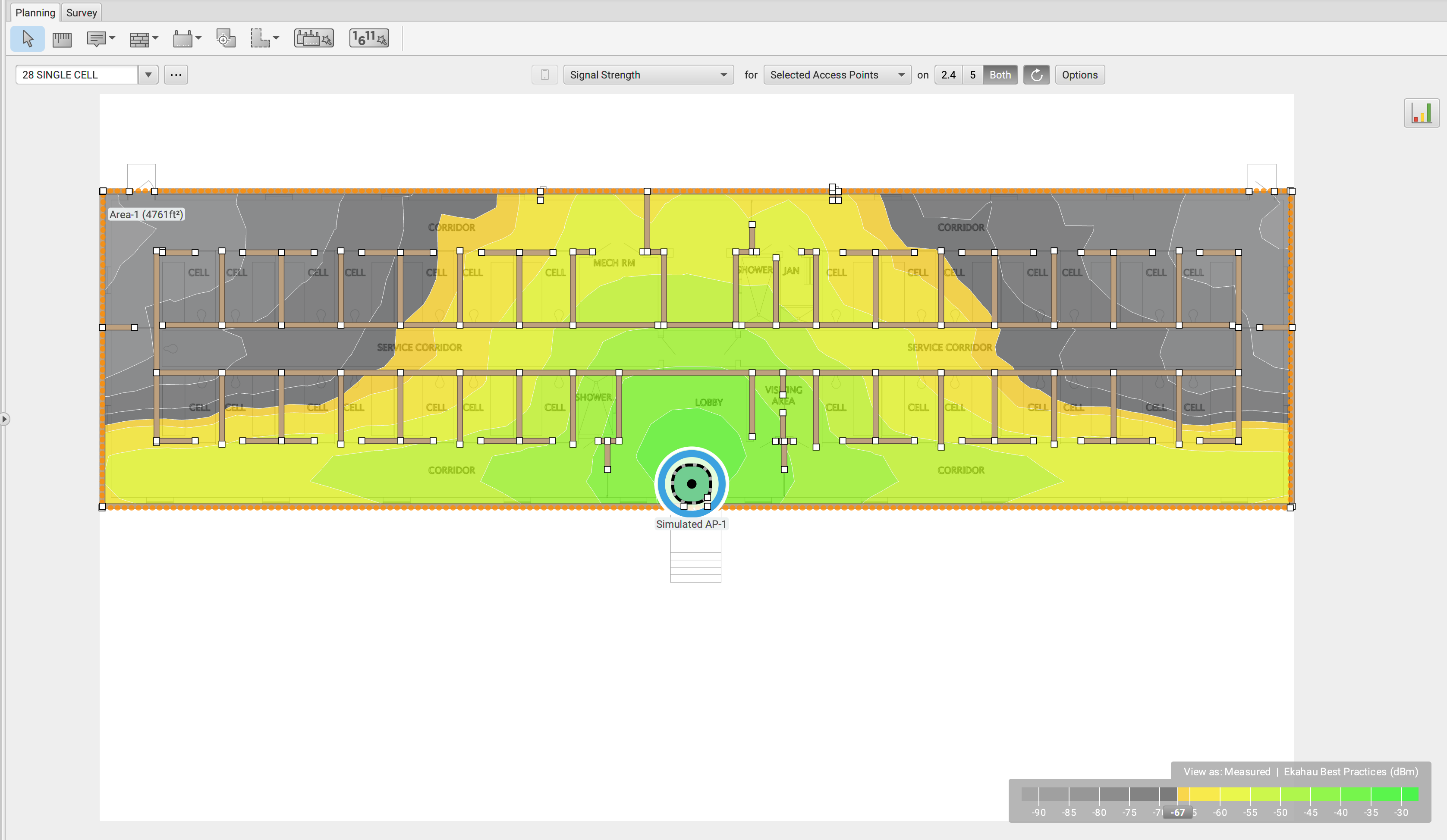
For picture two, we step it up a notch and change the wall types to resemble the attenuation of drywall. You can now see that we have drastically reduced our coverage, but with maybe two more APs, we could have full coverage.
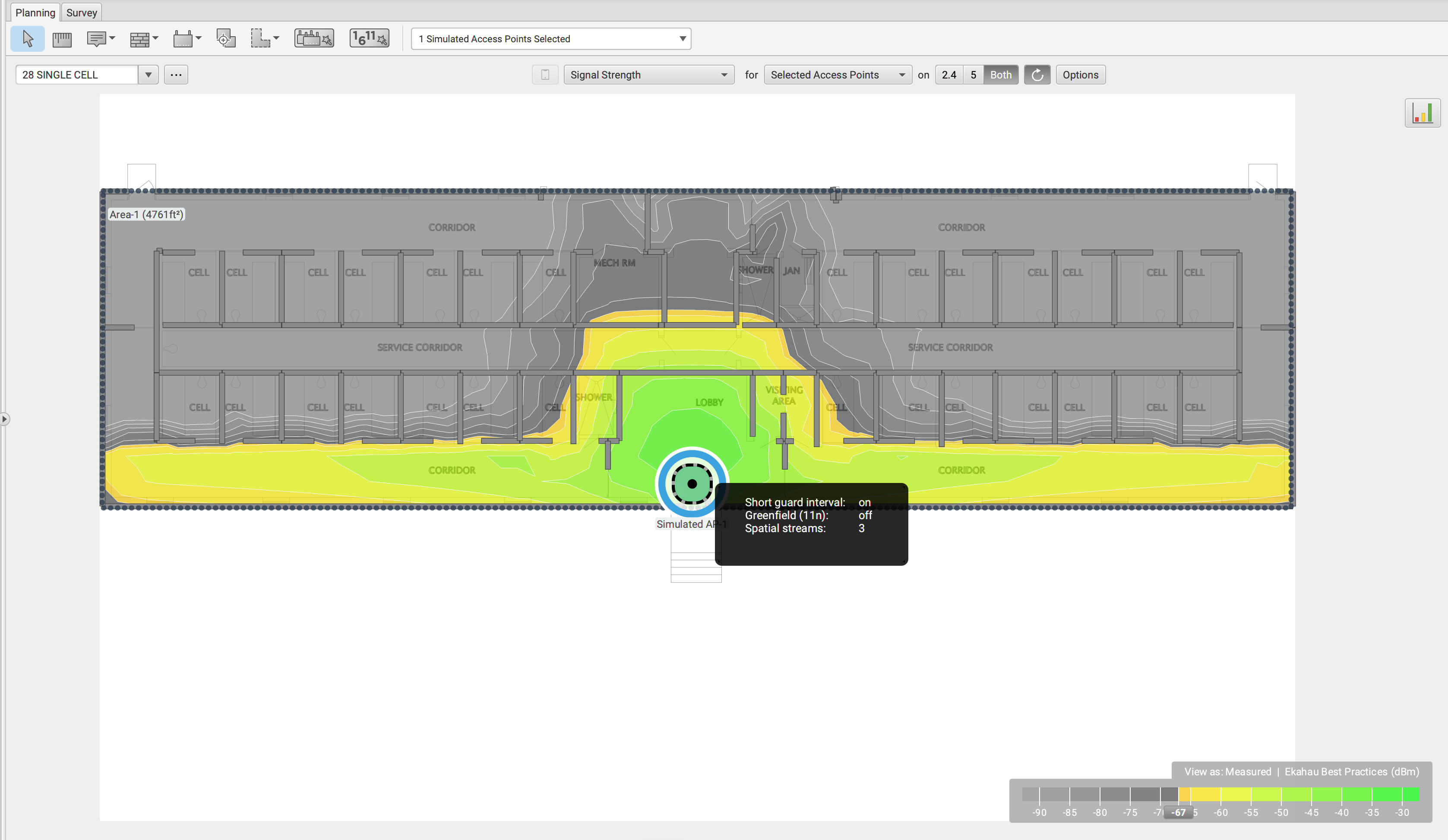
Finally for picture three, we take it to extremes and see what the likely real world scenario of these prison cells would look like. This now shows how severe the attenuation of concrete can be. Planning for scenarios like this are very difficult and take some time to get right. Remember when we talked about using walls as ways to shrink cell sizes. This should give you a good idea as to how that would be possible.
Antennas
Omnidirectional antennas cannot provide targeted coverage so for instances like libraries and warehouses, patch antennas can be used to direct the RF down aisles. Using directional antennas in very high density environments helps with CCI by not allowing the RF in big spaces to propagate to other APs on the same channel.
Outdoor Design
With outdoor design, we are typically not nearly as concerned with user density. This often requires a mesh deployment due to cable run restrictions. A typical use for outdoor wireless is point-to-point wireless bridges as described in Chapter 5.
Items of concern in outdoor deployments
- Lightning: Lightning arrestors should be used in outdoor deployments for protection against transient currents.
- Wind: With point-to-point links, wind can shift the antennas, so using a grid style antenna is recommended.
- Water: Connectors should be protected with drip loops and coax seals to prevent water seepage and damage. NEMA enclosures can also be used to protect outdoor bridges, APs and mesh APs.
- UV/Sun: Proper cable types are necessary to protect from UV rays.
Chapter Review
In this chapter we got into one of my favorite parts of WiFi, WLAN Design Concepts. I find designing WiFi to be super interesting. No two buildings are the same. Every design has some type of challenge that you may not have encountered before and figuring out how to work around those keeps you thinking. Every time you solve a unique problem, it helps you on the next one you encounter. We discussed how SNR is important to the viability of your Wifi, and how RSSI is not the only item to design for. We hit upon channel reuse and how important it is to avoid CCI and ACI by properly planning your channel layout. We also took a look at capacity planning and how we need to understand that in todays environments every person typically has more than one device, meaning head count is not a viable design factor, device count is.
Interesting Link of the Day
Keeping in line with the theme of the day: WLAN Design Concepts, I wanted to share a link to Ekahaus ECSE Design Training. Having gone through this class and earned the ECSE Design certification, I can tell you that it quite worth it. You start with the basics of WiFi to get a solid base from which to understand they why behind how Ekahau Pro works.


